Looking for vacuum hose diagrams
#21
 12-21-2011, 02:59 PM


the 3 vacume lines run under neath to a switch on the upper driver side, mid vehicle, to that switch located almost on top of the transfer case, one line is source from the pcv t" ,one goes to actuator underneath battery, and one runs along with the actuator line to cap/vent at end
it starts at pcv valve larger lin, goes to a t", one from ther to a canister in fender well under abs. then short 1'' piece to another t" that goes down to that switch on transfer case, one to a plastic line to hvac that mysteriously effects rear wiper.
from swith to the actuator, and one goes with to vent, other is from those t"s that is source.
that canister with nipple stickin out in the fender is like a resevoir so under hard suction/ accelertin, it pulls volume from ther, rather then effecting rest of system.
amazingly gm actually uses the tranfer case housing as a source for vacume when 4x4 not engaged
http://www.kylestubbins.com/files/im..._0.preview.jpg
Last edited by swartlkk; 12-21-2011 at 03:24 PM. Reason: *Combining Consecutive Posts* - Please use the edit function to add additional information in your post if another member has yet to respond.
#22
12-21-2011, 03:39 PM

looking for a diagram for the vaccum lines for the 4x4 system my uncle says theres a vaccum line that comes off the top of the engine conected to a 't' and it runs down the back of the block across the trans and from there i'm lost as well as he is he has to replace the vaccum lines for the 4wd actuator so the 4wd works can i get a diagram showing the lines or get a how to explaination on how to fix his problem? thanks would be much appreaciated
The first view shows the older vacuum actuated cruise servo so for the newer trucks, that can be ignored. The above is for the NV233/NV231 trucks. The NV236 vacuum diagram is different as the vacuum control for front axle engagement is handled by an electronic actuator located on the firewall so there are no vacuum lines back to the transfer case.
#23
12-22-2011, 05:56 AM
i guess it was just my understanding, i was thinking the switch screws into to the housing and when in 2 hi the ball valve is depressed, allowing the vacume to suck from the volume of the housing, and then they ran a seperat line off the housing to provide a vent.
when in 4 hi an arm moves away from the ball allowing it to spring into the down / sealed position, which pulls the actuator and cable.
was thinking
when in 4 hi an arm moves away from the ball allowing it to spring into the down / sealed position, which pulls the actuator and cable.
was thinking
#24
12-22-2011, 06:21 AM
The vent for the transfer case does tie in with the vent for the front axle actuator at the switch (vent port noted on the switch end view above), but that's it. It would be bad if either pressure or vacuum were allowed to exist in the t-case.
I'll see if I can get either some pictures taken of the vacuum switch I have cut apart or I may just model it in CAD later if I have time. It's hard to get pictures of the switch being all black plastic.
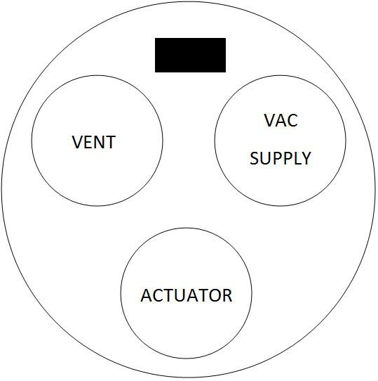
*EDIT* - So here's a rough CAD model of the black plastic portion of the vacuum switch used on the NV231 & NV233:


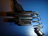
And here's some photos of the actual switch cut apart:


Basically, the vent port has a hole at the very bottom of the switch, closest to the ball end of the valve pintle. The vacuum supply port has a hole at the very top of the switch, closest to the vacuum lines. The hole for the port that runs to the actuator is smack in the middle. When the transfer case is in 2wd, the actuator port and the vent are open to each other between the o-rings in the valve pintle. When in 4wd, the valve pintle moves up, sealing off the vent port and opening up the vacuum port. Pretty simple thing, but once the o-rings go bad or the valve pintle freezes up, it stops working and causes problems with the front axle engagement. The kind of problem depends on where the valve froze.
I'll see if I can get either some pictures taken of the vacuum switch I have cut apart or I may just model it in CAD later if I have time. It's hard to get pictures of the switch being all black plastic.
*EDIT* - So here's a rough CAD model of the black plastic portion of the vacuum switch used on the NV231 & NV233:
And here's some photos of the actual switch cut apart:
Basically, the vent port has a hole at the very bottom of the switch, closest to the ball end of the valve pintle. The vacuum supply port has a hole at the very top of the switch, closest to the vacuum lines. The hole for the port that runs to the actuator is smack in the middle. When the transfer case is in 2wd, the actuator port and the vent are open to each other between the o-rings in the valve pintle. When in 4wd, the valve pintle moves up, sealing off the vent port and opening up the vacuum port. Pretty simple thing, but once the o-rings go bad or the valve pintle freezes up, it stops working and causes problems with the front axle engagement. The kind of problem depends on where the valve froze.
#26
12-23-2011, 08:47 AM
The transfer case vent line runs up and is attached to the transmission dip stick. The vacuum system to the actuator is not vented when in 4wd. All of the diagrams I have posted show the complete picture of the system.

Thread
Thread Starter
Forum
Replies
Last Post
cferry7
2nd Generation S-series (1995-2005) Tech
1
01-08-2015 01:35 PM
kakn
1st Generation S-series (1983-1994) Tech
4
07-22-2007 09:14 AM