99 blazer 4x4
#1
 04-08-2015, 03:07 PM


I have a 99 blazer and the 4x4 selector switch is not working or lighting up the only time it lights up is for a split second when I first turn the key on and the service 4x4 light is on what could be the problem?
#2
04-13-2015, 02:13 PM

Seriously though, if you want to diagnose, need to know 3 button or 4 button controls? (does it have the auto 4WD setting). This will determine what equipment you will need to have. Please advise what is your level of expertise with working on cars and electrical systems?
#3
04-13-2015, 09:58 PM
Its 4 button and I've checked all the fuses the only things I've done so far is clean the selector switch with electric part cleaner and put some Di-electric grease on the connectors of the switch and the TCCM. I thought it was the switch but it turns on for like half a second when I first turn the key on and I tried having Autozone hook up the scanner but they don't have one for the service 4x4, and im good with engines but not so much electrical systems. Before I go and buy a ton of parts id like to get an idea of what it could be and see if other people have had the same problem.
#4
04-14-2015, 08:40 AM
Its 4 button and I've checked all the fuses the only things I've done so far is clean the selector switch with electric part cleaner and put some Di-electric grease on the connectors of the switch and the TCCM. I thought it was the switch but it turns on for like half a second when I first turn the key on and I tried having Autozone hook up the scanner but they don't have one for the service 4x4, and im good with engines but not so much electrical systems. Before I go and buy a ton of parts id like to get an idea of what it could be and see if other people have had the same problem.
Unfortunately the only way to read TCCM codes on the NP8 4WD is through the data link and also it is reported that you must clear the 4WD codes after repairs before the system will operate correctly. So that is a concern. I was able to read/clear TCCM codes with a laptop and a $29 USB to OBD2 hardware device on mine, but this does require entering hexadecimal codes into an OBD2 terminal. It's not that bad, but definitely the bare bones way of communication and you need to be a bit of a nerd. For me it was quite a bit of fun to communicate with the TCCM this way (like I was doing something General Motors didn't want me to be able to do - I felt quite devious and sneaky, like I had just hacked into their system!)
That said you can get a pretty good idea of what is functioning and what is not, simply by testing with a multimeter at the TCCM - but you have to understand exactly how each circuit operates and there are a lot of circuits to consider. Are you up to it and willing to stay with the diagnosis until the bitter end?
If so, start by checking all the fuses and report please. (I lifted the following from the Captain's recent post to another person)
There are 5 fuses for the 4WD system.
In the instrument panel fuse panel:
4WD fuse #15 10amp must show battery voltage in the RUN position.
CTSY LP fuse #8 10 amp must show battery voltage at all times.
In the underhood fuse panel:
ATC fuse 20 amp must show battery voltage at all times.
BTSI fuse 10 amp must show battery voltage in PARK & NEUTRAL.
CRANK fuse 10 amp must show battery voltage in the START position.
Do not remove the fuses while testing. Test both terminals on the top of each fuse.
Last edited by LesMyer; 04-14-2015 at 09:23 AM.
#5
04-14-2015, 01:22 PM
Here's the RPO NP8 system description for you to read through:
Transfer Case Description and Operation
The NVG 236/246 transfer case features a 4 button shift control switch located on the instrument panel. When the vehicle has the ignition key in the RUN position, the transfer case shift control module starts monitoring the Transfer case shift control switch to determine if the driver desires a new mode/gear position. At a single press of the transfer case shift control switch, the lamp of the new desired position will begin flashing to inform the driver that the transfer case shift control module has received the request for a new mode/gear position. The lamp will continue to flash until all shifting criteria has been met and the new mode/gear position has been reached (or has been engaged). Once the new mode/ gear position is fully active, the switch indicator lamp for the new position will remain ON constantly. During normal driving situations the transfer case can operate in the Auto 4WD mode. In the Auto 4WD mode the transfer case shift control module monitors rear wheel slip speed (based on the inputs from both the front and rear propshaft speed sensors). When the vehicle experiences a rear wheel slip condition, the transfer case shift control module sends a Pulse Width Modulated (PWM) signal to an electronic motor (transfer case encoder motor). This motor rotates the transfer case sector shaft, applying a clutch pack. This clutch pack is designed to deliver a variable amount of torque (normally delivered to the rear wheels) and transfers it to the front wheels. Torque is then ramped up to the front wheels until the front propshaft speed sensor matches that of the rear propshaft speed sensor. Torque is then ramped down until torque is completely removed from the front wheels or until rear wheel slip is once again detected (the process would then repeat). The NVG 236/246 transfer case has the added feature of also providing the driver with 3 manual mode/gear positions:
Transfer Case Shift Control Module
The transfer case shift control module uses the VIN information for calculations that are required for the different calibrations used based on axle ratio, transmission, tire size, and engine. The system does not know which calibration to use without this information. This information is provided to the transfer case shift control module via Class 2 data bus from the Powertrain Control Module (PCM).
The transfer case shift control module monitors front and rear propshaft speed as well as controlling the operation of the transfer case encoder motor assembly and the engaging and disengaging of the front axle.
Transfer Case Encoder Motor
The transfer case encoder motor consists of a Permanent Magnet (PM) DC motor and gear reduction assembly. It is located on the left hand side of the transfer case. When activated it turns the sector shaft of the transfer case (clockwise or counter clockwise) to shift the transfer case and to apply the clutch that applies the front propshaft. The encoder motor is controlled with a Pulse Width Modulated (PWM) circuit provided by the transfer case shift control module. This circuit consists of a driver on both the Motor Control A and Motor Control B circuits. The encoder motor is bi-directional to allow the motor to shift the transfer case from 2HI or 4HI to NEUTRAL and 4LO positions.
The transfer case encoder motor can be turned ON and OFF using a scan tool. You may also monitor Motor Control A and B circuits using a scan tool.
Transfer Case Encoder
The encoder is mounted to the transfer case encoder motor assembly and is replaced only as an assembly. The encoder converts the sector shaft position (representing a mode or range) into electrical signal inputs to the transfer case shift control module. The module detects what position the transfer case is in by monitoring the 4 encoder channels (P. A,B, and C). These inputs translate into AUTO 4WD, 2HI, 4HI, NEUTRAL, and 4LO or whether the motor is still in transition between gears.
The transfer case encoder channel circuits may be monitored using a scan tool.
Transfer Case Motor Lock
The transfer case motor lock is used to prevent the transfer case from changing mode/gear positions or popping out of position when the vehicle is in 2HI, 4HI, and 4LO. When the lock circuit is energized, the transfer case encoder motor is allowed to rotate. When the transfer case is placed PHI, 4HI, or 4LO the motor lock circuit has no voltage provided to it (applying the lock) which assures that the transfer case remains in the current mode/gear position. When AUTO 4WD is selected the motor lock remains applied until an adaptive mode (torque is applied to the front propshaft) is required. During an adaptive mode the motor lock circuit is energized (locking mechanism is released), enabling the encoder motor to turn and apply torque to the front propshaft.
The transfer case motor lock circuit can be turned ON and OFF using a scan tool. You may also monitor the lock circuit using a scan tool.
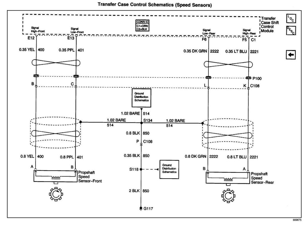
Transfer Case Speed Sensors
There are three speed sensors mounted on the transfer case, two on the rear output shaft and one on the front output shaft. Each speed sensor is a Permanent Magnet (PM) generator. The PM generator produces a AC voltage. The AC voltage level and number of pulses increases as speed increases.
Vehicle Speed Sensor
One of the two speed sensors on the rear output shaft is the Vehicle Speed Sensor (VSS) input to the Powertrain Control Module (PCM) . The PCM sends this information to the transfer case shift control module via the Class 2 serial data bus.
Rear Propshaft Speed Sensor
The transfer case shift control module converts the pulsating AC voltage from the rear transfer case speed sensor to a rear propshaft speed in RPM to be used for calculations. The rear propshaft speed can be displayed with a scan tool.
Front Propshaft Speed Sensor
The transfer case shift control module converts the pulsating AC voltage from the front transfer case speed sensor to front propshaft speed in RPM to be used for calculations, and to monitor the difference between the front and rear sensor speed. It is also used in the AUTO 4WD mode to determine the amount of slip and the percent of torque to apply to the front axle. The front propshaft speed can be displayed with a scan tool.
SERVICE Indicator (4WD/AWD) Lamp
The SERVICE indicator (4WD/AWD) lamp is an integral part of the cluster and cannot be serviced separately. This lamp is used to inform the driver of the vehicle of malfunctions within the Automatic Transfer Case (ATC) system. The SERVICE indicator (4WD/AWD) lamp is controlled by the transfer case shift control module via a Class 2 message or by a Service Indicator Control circuit.
Transfer Case Description and Operation
The NVG 236/246 transfer case features a 4 button shift control switch located on the instrument panel. When the vehicle has the ignition key in the RUN position, the transfer case shift control module starts monitoring the Transfer case shift control switch to determine if the driver desires a new mode/gear position. At a single press of the transfer case shift control switch, the lamp of the new desired position will begin flashing to inform the driver that the transfer case shift control module has received the request for a new mode/gear position. The lamp will continue to flash until all shifting criteria has been met and the new mode/gear position has been reached (or has been engaged). Once the new mode/ gear position is fully active, the switch indicator lamp for the new position will remain ON constantly. During normal driving situations the transfer case can operate in the Auto 4WD mode. In the Auto 4WD mode the transfer case shift control module monitors rear wheel slip speed (based on the inputs from both the front and rear propshaft speed sensors). When the vehicle experiences a rear wheel slip condition, the transfer case shift control module sends a Pulse Width Modulated (PWM) signal to an electronic motor (transfer case encoder motor). This motor rotates the transfer case sector shaft, applying a clutch pack. This clutch pack is designed to deliver a variable amount of torque (normally delivered to the rear wheels) and transfers it to the front wheels. Torque is then ramped up to the front wheels until the front propshaft speed sensor matches that of the rear propshaft speed sensor. Torque is then ramped down until torque is completely removed from the front wheels or until rear wheel slip is once again detected (the process would then repeat). The NVG 236/246 transfer case has the added feature of also providing the driver with 3 manual mode/gear positions:
- 4HI - 4 Wheel Drive high range
- 2HI - 2 Wheel Drive high range
- 4LO - 4 Wheel Drive low range The driver may choose to select any of these mode/gear positions while driving the vehicle. However, the transfer case will not allow a shift into or out of 4LO unless the following criteria has been met:
- The engine is running.
- The automatic transmission is in Neutral (clutch depressed on manual transmissions).
- The vehicle speed is below 5 km/h (3 mph) . This transfer case also has a Neutral position. A shift to the Neutral position allows the vehicle to be towed without the rear axle rotating the transfer case main shaft and the transmission output shaft. Neutral position may be obtained only if the following criteria has been met:
- The engine is running.
- The automatic transmission is in Neutral (clutch depressed on manual transmissions).
- The vehicle speed is below 5 km/h (3 mph).
- The transfer case is in 2HI mode. Once these conditions have been met, press and hold both the 2HI and 4LO buttons for 10 seconds. When the system completes the shift to neutral, the red neutral lamp will illuminate.
Transfer Case Shift Control Module
The transfer case shift control module uses the VIN information for calculations that are required for the different calibrations used based on axle ratio, transmission, tire size, and engine. The system does not know which calibration to use without this information. This information is provided to the transfer case shift control module via Class 2 data bus from the Powertrain Control Module (PCM).
The transfer case shift control module monitors front and rear propshaft speed as well as controlling the operation of the transfer case encoder motor assembly and the engaging and disengaging of the front axle.
Transfer Case Encoder Motor
The transfer case encoder motor consists of a Permanent Magnet (PM) DC motor and gear reduction assembly. It is located on the left hand side of the transfer case. When activated it turns the sector shaft of the transfer case (clockwise or counter clockwise) to shift the transfer case and to apply the clutch that applies the front propshaft. The encoder motor is controlled with a Pulse Width Modulated (PWM) circuit provided by the transfer case shift control module. This circuit consists of a driver on both the Motor Control A and Motor Control B circuits. The encoder motor is bi-directional to allow the motor to shift the transfer case from 2HI or 4HI to NEUTRAL and 4LO positions.
The transfer case encoder motor can be turned ON and OFF using a scan tool. You may also monitor Motor Control A and B circuits using a scan tool.
Transfer Case Encoder
The encoder is mounted to the transfer case encoder motor assembly and is replaced only as an assembly. The encoder converts the sector shaft position (representing a mode or range) into electrical signal inputs to the transfer case shift control module. The module detects what position the transfer case is in by monitoring the 4 encoder channels (P. A,B, and C). These inputs translate into AUTO 4WD, 2HI, 4HI, NEUTRAL, and 4LO or whether the motor is still in transition between gears.
The transfer case encoder channel circuits may be monitored using a scan tool.
Transfer Case Motor Lock
The transfer case motor lock is used to prevent the transfer case from changing mode/gear positions or popping out of position when the vehicle is in 2HI, 4HI, and 4LO. When the lock circuit is energized, the transfer case encoder motor is allowed to rotate. When the transfer case is placed PHI, 4HI, or 4LO the motor lock circuit has no voltage provided to it (applying the lock) which assures that the transfer case remains in the current mode/gear position. When AUTO 4WD is selected the motor lock remains applied until an adaptive mode (torque is applied to the front propshaft) is required. During an adaptive mode the motor lock circuit is energized (locking mechanism is released), enabling the encoder motor to turn and apply torque to the front propshaft.
The transfer case motor lock circuit can be turned ON and OFF using a scan tool. You may also monitor the lock circuit using a scan tool.
Transfer Case Speed Sensors
There are three speed sensors mounted on the transfer case, two on the rear output shaft and one on the front output shaft. Each speed sensor is a Permanent Magnet (PM) generator. The PM generator produces a AC voltage. The AC voltage level and number of pulses increases as speed increases.
Vehicle Speed Sensor
One of the two speed sensors on the rear output shaft is the Vehicle Speed Sensor (VSS) input to the Powertrain Control Module (PCM) . The PCM sends this information to the transfer case shift control module via the Class 2 serial data bus.
Rear Propshaft Speed Sensor
The transfer case shift control module converts the pulsating AC voltage from the rear transfer case speed sensor to a rear propshaft speed in RPM to be used for calculations. The rear propshaft speed can be displayed with a scan tool.
Front Propshaft Speed Sensor
The transfer case shift control module converts the pulsating AC voltage from the front transfer case speed sensor to front propshaft speed in RPM to be used for calculations, and to monitor the difference between the front and rear sensor speed. It is also used in the AUTO 4WD mode to determine the amount of slip and the percent of torque to apply to the front axle. The front propshaft speed can be displayed with a scan tool.
SERVICE Indicator (4WD/AWD) Lamp
The SERVICE indicator (4WD/AWD) lamp is an integral part of the cluster and cannot be serviced separately. This lamp is used to inform the driver of the vehicle of malfunctions within the Automatic Transfer Case (ATC) system. The SERVICE indicator (4WD/AWD) lamp is controlled by the transfer case shift control module via a Class 2 message or by a Service Indicator Control circuit.
#6
04-14-2015, 01:32 PM
Here's the wiring schematics for a 2001 Blazer with RPO=NP8. Yours should be identical or almost identical (few colors might possibly be different). I will be referring to these later. Don't let them intimidate you:
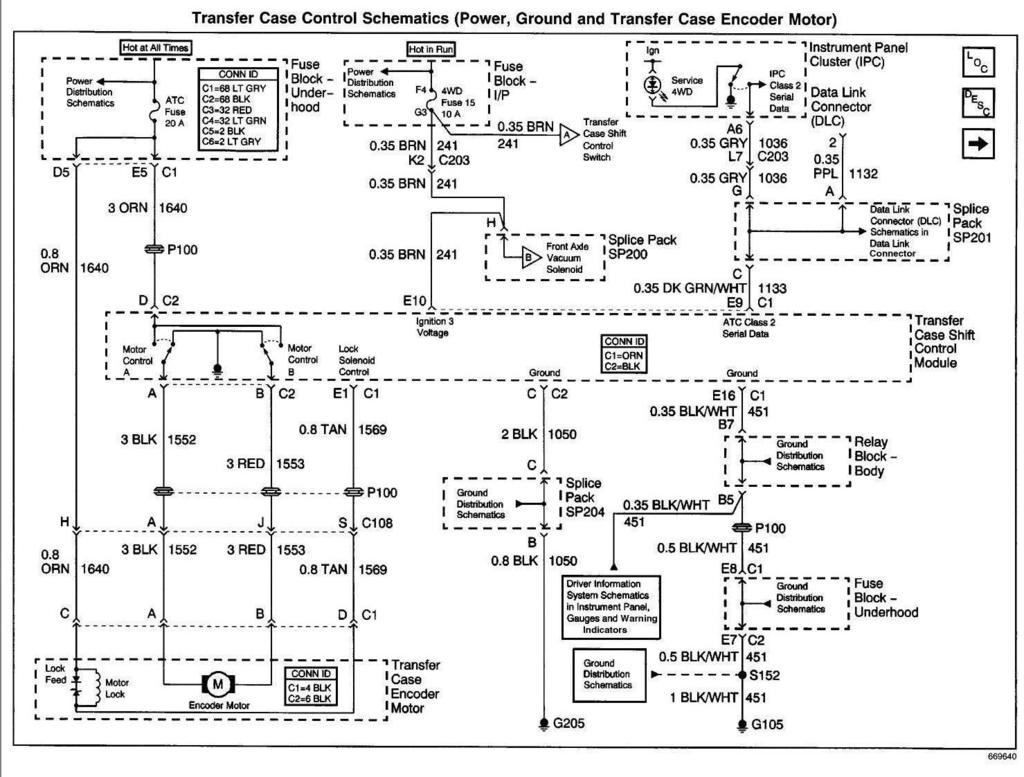
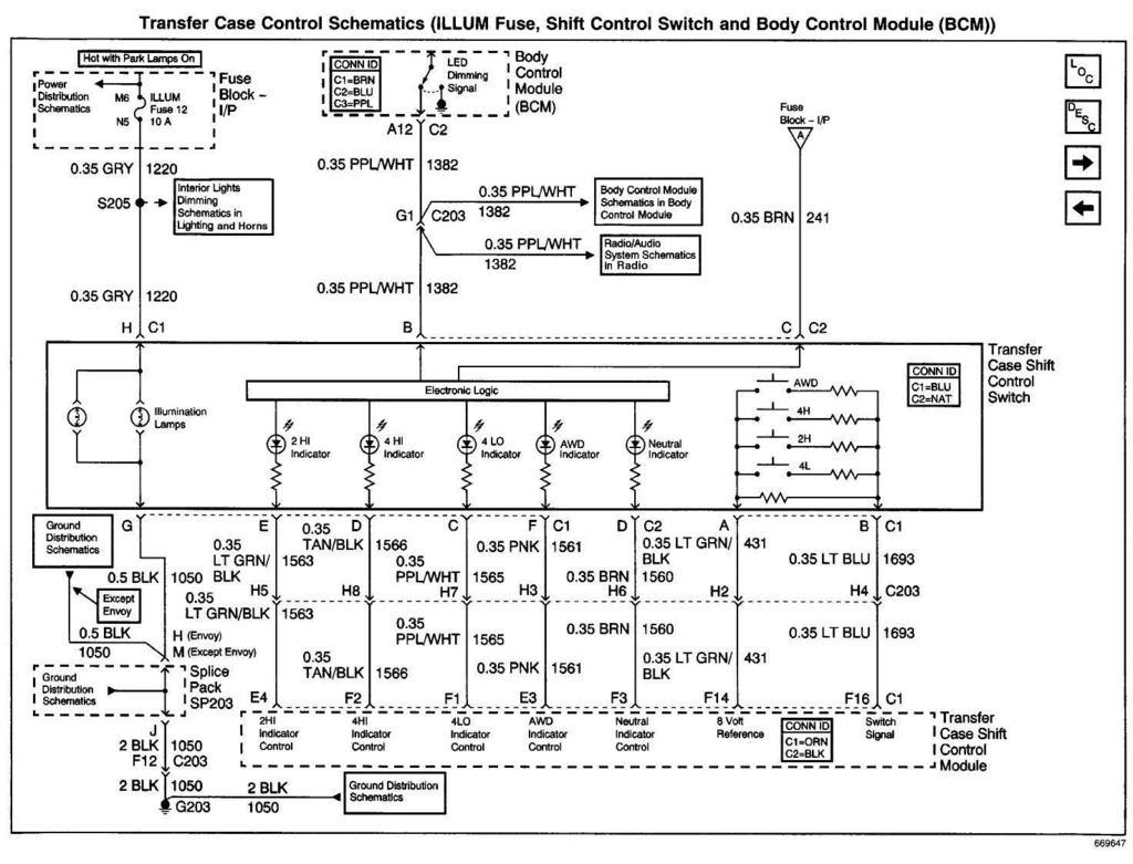
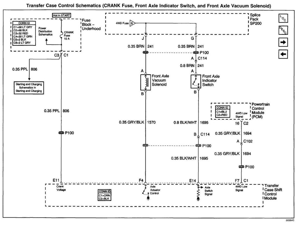
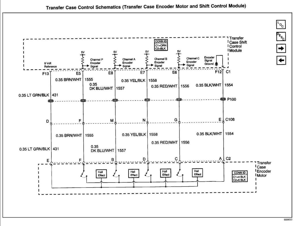
Last edited by LesMyer; 04-14-2015 at 01:49 PM.
#7
04-14-2015, 02:02 PM
Below is lifted from an old post by Swartlkk at https://blazerforum.com/forum/2nd-ge...d-24964/page3/. This shows the resistance that should be observed when different buttons are pressed on the contols. We may have use for it later.
-----------------------------------
For the resistance, you have to use the parallel resistance formula:
In this case, there are only two parallel resistors when only one button is pushed.
The resistance between connector 1 pins A & B are as follows for single button push:
Just for others that take a look at this thread later on, this is for the Auto4wd (NP8) NV236 transfer case shift control switch only. The NV233 (NP1) transfer case is a direct connection with dedicated wires for the different modes and is easier to test.
-----------------------------------
For the resistance, you have to use the parallel resistance formula:
In this case, there are only two parallel resistors when only one button is pushed.
The resistance between connector 1 pins A & B are as follows for single button push:
- No buttons pushed - 9.09kOhm (9090 Ohm)
- 4Low pushed - 2.345kOhm (2345 Ohm)
- 2High pushed - 1.516kOhm (1516 Ohm)
- 4High pushed - 0.663kOhm (663 Ohm)
- Auto4WD pushed - 0.064kOhm (64 Ohm)
Just for others that take a look at this thread later on, this is for the Auto4wd (NP8) NV236 transfer case shift control switch only. The NV233 (NP1) transfer case is a direct connection with dedicated wires for the different modes and is easier to test.
#8
04-17-2015, 10:57 AM
OK here's the answer that he really wanted to hear.
"At one point mine was doing the same this as yours. The 4WD light was on and control button lights were going out. Took both an Encoder Motor and a TCCM to fix it". .... and chances are if he puts both in he has a good chance of fixing the problem, as long as his fuses are Transfer case are actually good. They are pretty pricey parts.
But I really doubt his problem is the same, even though the symptoms are the same. The symptoms he described are generic for a lot of 4WD troubles.
Guess I wasted my time trying to truly help diagnose.
Last edited by LesMyer; 04-17-2015 at 11:01 AM.

Thread
Thread Starter
Forum
Replies
Last Post
tdbone1
2nd Generation S-series (1995-2005) Tech
15
11-30-2012 06:53 PM
Tinted
2nd Generation S-series (1995-2005) Tech
35
02-07-2011 01:12 PM
BaLListic_Evo
2nd Generation S-series (1995-2005) Tech
3
06-04-2010 03:38 PM
razman
Steering, Suspension & Drivetrain
11
02-22-2009 01:57 PM