Electrical Diagrams?
#1
 01-20-2012, 11:14 AM


Howdy,
I'm in the process of eliminating wiring in the engine compartment. Plan is to run 1-wire alternator and clean up the engine harness in general.
I'm looking for help identifying the main power wires going into the engine harness and their power requirements.
Thanks in advance,
Steve
I'm in the process of eliminating wiring in the engine compartment. Plan is to run 1-wire alternator and clean up the engine harness in general.
I'm looking for help identifying the main power wires going into the engine harness and their power requirements.
Thanks in advance,
Steve
#2
01-20-2012, 12:05 PM

Wa'al I'm jest an ol' geezer and I herda this thing called googly or sump'n. So I typed 70 chevy truck wiring into that there box on the upper right'a this hyar window and got a buncha lines.. so I looked around and saw this 'images' label ...I clickied on it and looky here!
http://www.justanswer.com/uploads/cr...114449_ja1.JPG
So it's sorta small I I wondered what to do now and alla sudden my palsy kicked in and when my finger jumped it pushed the other button on that there rat or whate'er and little box had line in it said "save image as" so I clicked on it and it let me put taht picture of all them wires on my main screen.. some call it a desktop.. even thought there aint no place for my Morgan and Coke.


All BS aside: That looks pretty comprehensive as I scanned it, but one important thing. There's no coil resistor shown, so I assume it's under the dash. Coil resistor is necessary as hell. Make sure you dont do anything to anything attached to Coil +
PPS: If it were me, I'd tie back the brown wire to the VR instead of cutting it. If I'm right that goes to 'gen lite' and might work right if you hook it to the S terminal.
http://www.justanswer.com/uploads/cr...114449_ja1.JPG
So it's sorta small I I wondered what to do now and alla sudden my palsy kicked in and when my finger jumped it pushed the other button on that there rat or whate'er and little box had line in it said "save image as" so I clicked on it and it let me put taht picture of all them wires on my main screen.. some call it a desktop.. even thought there aint no place for my Morgan and Coke.
All BS aside: That looks pretty comprehensive as I scanned it, but one important thing. There's no coil resistor shown, so I assume it's under the dash. Coil resistor is necessary as hell. Make sure you dont do anything to anything attached to Coil +
PPS: If it were me, I'd tie back the brown wire to the VR instead of cutting it. If I'm right that goes to 'gen lite' and might work right if you hook it to the S terminal.
Last edited by pettyfog; 01-20-2012 at 12:51 PM.
#3
01-20-2012, 01:12 PM
Um... The 1970 diagram is great and all but I'm chopping the wires on my 86. Soooo.... I guess I should have clarified that in my first post.
This is what I'm looking for help with... the red wires that head to the starter + post and the alternator. Specifically wondering if omitting the brown wire (voltage signal wire) will cause problems.
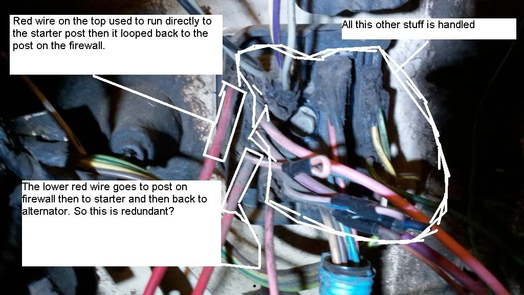
This is what I'm looking for help with... the red wires that head to the starter + post and the alternator. Specifically wondering if omitting the brown wire (voltage signal wire) will cause problems.
Last edited by swartlkk; 01-20-2012 at 02:51 PM. Reason: *Combining Consecutive Posts* - Please use the edit function to add additional information in your post if another member has yet to respond.
#4
01-20-2012, 02:41 PM
Wow.. I get your point.. what a mess.
What I would suggest is Simplifying everything. Look up the 'Big Three' mods.
From Batt Positive terminal:
- To Alt with appropriate size fuse link 4- 6 ga min
- To Starter positve post: big sucker
- To terminal of fuse block: 4-6 gauge *
* So, I assume that's what those two red wires are and that they're always 'live'. Take them both to the battery terminal. Only thing it might affect is if you have 'Ammeter' That was probably why the loop. I of course suggest voltmeter instead. More accurate for indicating electrical status
None of those needs be tied together, otherwise. To delete. Install above clean, cut wire.. everything works then remove it all
From batt term neg:
- big sucker to engine block
- 6- 8 ga min to radiator support or fender
- I suggest, also, 6-8 ga to frame
And a strap from engine block or head to firewall.
Now... on your starter solenoid.. one or two small terminals? Refer to the 70 diagram. On there, the second is to short out the coil resistor to give more spark during crank.
If it's 86, doesnt it have HEI ignition? Been long time but IIRC the circuit is different for HEI. and the second small terminal on sol went away
Is that the 'brown' wire.. or is brown only live during crank. Meant to engage solenoid?
Last edited by pettyfog; 01-20-2012 at 03:02 PM.
#5
01-20-2012, 03:17 PM
Dumpti-dum, you've got my head turning now... been working and researching this for about a week now. It all started because I wanted to move heater hose from on top of my water neck back to the manifold... Now I've got no inner fenders, all the ignition and engine harness cut apart... so much for a little job...
I searched for the "big three" mods, didn't find anything obvious in the results, can you point me in the right direction?
After finding some technical articles, MadElectrical.com - Mad Enterprises , I'm reconsidering the one wire route. Even though there is more complexity with a three wire system it might be worth it due to performance and cheaper since I don't need to replace my perfectly good alternator..
#6
01-20-2012, 03:20 PM
Now... on your starter solenoid.. one or two small terminals? Refer to the 70 diagram. On there, the second is to short out the coil resistor to give more spark during crank.
If it's 86, doesnt it have HEI ignition? Been long time but IIRC the circuit is different for HEI. and the second small terminal on sol went away
Is that the 'brown' wire.. or is brown only live during crank. Meant to engage solenoid?
If it's 86, doesnt it have HEI ignition? Been long time but IIRC the circuit is different for HEI. and the second small terminal on sol went away
Is that the 'brown' wire.. or is brown only live during crank. Meant to engage solenoid?
#7
01-20-2012, 03:54 PM
I have a redundant starter relay on my tbird.. just confuses people and extra fail point, I wired around it.
#8
01-20-2012, 04:25 PM
External solenoid would let me run just one beefy wire to the starter. Would allow me to have all components in one place for ease of fixing on the trail. And would avoid the heat soak issue that is common with headers. I run this rig off road so there isn't much airflow around the exhaust when i'm crawling up trails. The last thing I want is to be dead on a trail.

Thread
Thread Starter
Forum
Replies
Last Post
Jon62
2nd Generation S-series (1995-2005) Tech
27
12-23-2011 07:16 PM
kakn
1st Generation S-series (1983-1994) Tech
4
07-22-2007 09:14 AM
1986, 86, 87, alternator, blazer, chart, chevy, dash, diagram, electrical, k5, label, schematics, wire, wiring