96 alternator wiring
#1
 01-09-2012, 04:10 PM


I have a 1996 blazer 4wd and im frying alternators. There are two sets of wires that confuses me. The RED/w the boot. (I know this one has to go to the stud at the back of the ALT) And a green and black wire. After the second ALT the guy at autozone there should be only one wire going to the ALT. Red wire is reading 12v from the bat and the green wire 0v. When i connect the red and the green/black wire to the back of the ALT i get power and able to crank the engine.(But also frying ALTS)
Can someone please help me?
Can someone please help me?
#2
01-25-2012, 08:31 AM

the black and green wire are ground wires. the only wire that should be coming out of ur alternator is the red one with a boot. alternators only produce a charge therefore they need to be grounded you need to put the black and the green on your negative terminal of the battery. if it doesnt start check where those wires go. one should go to the frame and the other goes to your engine block
#4
01-25-2012, 11:03 AM

Hold on...
Before you jump to conclusions about what is and is not needed for the alternator how about a little research! This is for early eighties era GM alts but it is typical for basic alt wiring.
BEFORE 97!
The big-*** red wire always goes to the big insulated stud on the alternator. If you can screw that up you shouldnt be working on that stuff.
For single wire that's all you need. Hopefully you have a 'volt' gauge in your dash.
Now for the OP:
Put your DVM to the wires you have questions on. If one ALWAYS has 0 volts, whether key is in run or off, then ohm it out. Less than 2 ohms, it is likely a ground.
A Black wire in GM wiring is almost always ground. Measure it with an ohmmeter.
Be careful what you hook it to. Any bolt or stud on the alternator case should be okay,
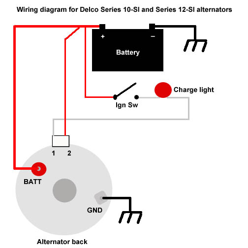
If 1 of them is always 12 volts {see #2 on the image} it's battery reference. Many alternators connect this internally to just look at the output, ie the big stud.
The #1 connection on the image is very typical.
That connection will show 12v with key in run position only. That could be the green wire.
It serves two purposes:
Provides 'excite' voltage to start your alternator charging
Shows, by lighting the battery or alt lite in the cluster, when something is wrong inside alternator causing it to not charge.
Again.. this does not apply to 97 and later.
Before you jump to conclusions about what is and is not needed for the alternator how about a little research! This is for early eighties era GM alts but it is typical for basic alt wiring.
BEFORE 97!
The big-*** red wire always goes to the big insulated stud on the alternator. If you can screw that up you shouldnt be working on that stuff.
For single wire that's all you need. Hopefully you have a 'volt' gauge in your dash.
Now for the OP:
Put your DVM to the wires you have questions on. If one ALWAYS has 0 volts, whether key is in run or off, then ohm it out. Less than 2 ohms, it is likely a ground.
A Black wire in GM wiring is almost always ground. Measure it with an ohmmeter.
Be careful what you hook it to. Any bolt or stud on the alternator case should be okay,
If 1 of them is always 12 volts {see #2 on the image} it's battery reference. Many alternators connect this internally to just look at the output, ie the big stud.
The #1 connection on the image is very typical.
That connection will show 12v with key in run position only. That could be the green wire.
It serves two purposes:
Provides 'excite' voltage to start your alternator charging
Shows, by lighting the battery or alt lite in the cluster, when something is wrong inside alternator causing it to not charge.
Again.. this does not apply to 97 and later.
#5
01-25-2012, 12:13 PM

99% of the time the guys behind the counter are not qualified to rotate the air in your tires. There are a few good mechanics that can offer advice, but they are rare and should be paid the wages of a certified mechanic...
I've been studying the 3-wire alternator system, it is simple concept. One large wire leaves the alternator to charge the system. Typically it is connected to a junction at the same place as another wire from the alternator that sense's the voltage at that junction and tells the alt when to turn on and when to turn off. The third wire is for a gauge light on the dash.

Thread
Thread Starter
Forum
Replies
Last Post
leroysfishingteam
Lighting & Electrical
4
02-12-2015 09:40 PM
rsturton
2nd Generation S-series (1995-2005) Tech
2
03-31-2010 09:02 AM
mnwhlp
2nd Generation S-series (1995-2005) Tech
5
01-17-2008 11:10 AM