Locating the VSS sensor
#1
 03-01-2009, 05:23 PM


ok so heres my question,
I am getting ready to wire up my over head consol and i have a question about a wire tap i need to do. I need to tap into the VSS sensor for the temp readoutand im wondering where i can access the wire on my 2003 and where my CPU is actually located. In the instructions i am going off of it states the connector is labled black on the connector and splice into pin 3. but im lost after that. any help would be apreciated. Thanks.
Also here is the link to the thread im following.
http://www.s10forum.com/forum/f200/o...nstall-214399/

#5
03-22-2009, 06:35 PM
ok, i know this sounds stupid but is the VSS in the bunch of wires connected to the PCM?
#8
03-22-2009, 07:01 PM
Here is what I could find...
Connector 1 (BLUE):


Connector 2 (GREEN):


Then specifically about the VSS input and output to the cluster:
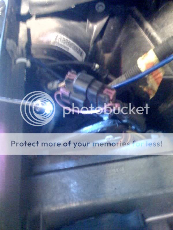
The wire I think you would want would be the high input from the VSS sensor which is the purple w/ white tracer wire located at pin 21 of connector 2.
As there is obviously speed output to the cluster, I would think it would be easier to get the signal from inside the cab, but that how-to you linked to seemed like it wanted the data straight from the VSS sensor itself.
Connector 1 (BLUE):

Connector 2 (GREEN):

Then specifically about the VSS input and output to the cluster:

The wire I think you would want would be the high input from the VSS sensor which is the purple w/ white tracer wire located at pin 21 of connector 2.
As there is obviously speed output to the cluster, I would think it would be easier to get the signal from inside the cab, but that how-to you linked to seemed like it wanted the data straight from the VSS sensor itself.

Thread
Thread Starter
Forum
Replies
Last Post
Tvojtko
1st Generation S-series (1983-1994) Tech
1
03-06-2013 07:40 PM
svd85
2nd Generation S-series (1995-2005) Tech
2
11-28-2009 09:10 AM

