
Obd1 port pin assignment 92 blazer


Thread Starter
|
Starting Member
Joined: Jan 2011
Posts: 207

I need a pin assignment for my obd1 port. I can see there are 7 pins in the 12 pin connector and can only find information on 4 of the 7.
thanks
here's what I found so far:
A= Ground
B= ALDL data from ECM/codes only
C= Canister purge solenoid(for testing)
D= Not used
E= Serial Data(for scam tool data)
F= TCC(automatic trans) or O/D relay(standard trans)
G= Fuel pump

Pin M is 8192 baud?
I am thinking about using this circuit .... what is the reason for using 160 baud over 8192?
160 Baud ALDL Hardware Interface
The ECM produces the data signal at either a 12 Volt or 5 volt level that must be inverted and converted to RS232. One simple scheme is to feed the ALDL data into a single transistor level converter that inverts the data to produce a pseudo RS232 level (varies between 12 Volts and 0). This is connected to the receive data line of a serial port to be processed by the PC's UART.
R3
When you build the cable first try without the R3 resistor. That works for most vehicles. Some vehicles need a 10k resistor to start transmitting data but the resistor will change the ECM's mode. It will have a high idle and spark knock retard will be disabled. That is the reason why you should not use the R3 resistor if it works without it.
R4
With this resistor installed the interface will NOT work with fuel injected vehicles. This resistor should ONLY be used with some carbed vehicles that does not work with the standard interface. If you need this resistor then you probably have to use the 4800 baud setting in the configuration too.
This circuit is using the 8192 pin.

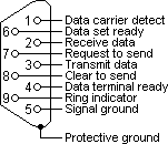
Here's the rs232 pin assignment just for reference
ALDL Terminals
Terminals "A" and "B"
These terminals are the only ones used to activate the self-diagnostics mode. Terminal A is grounded to the body chassis. Terminal B is routed back through the under dash connector, to ecm terminal A9. Connecting A and B together, with the ignition key in the "on" position, engine not running will activate the diagnostic mode (explained later). This mode used while the engine is running is used to monitor the O2 sensor for proper operating status. Leaving these terminals unconnected is the normal driving mode.
Connecting a 3.9K ohm resistor across these terminals will call for ecm to go into back up mode. The ecm will use only the tps, engine speed, and cst to activate the injectors. This mode is automatically activated when there is a major ecm failure. Instructions on the calpak is used. Another mode is activated when a 10K ohm resistor is connected to these terminals. This mode will force the ecm to go into close loop, ignoring the internal timer, and fixes the engine speed around 1000 rpm with a fixed iac position. Using this mode can be helpful when trying to diagnose a unstable idle. With the iac position fixed, if the idle still continue to fluctuate, you can rule out a faulty iac motor.
Terminal "C"
This terminal is used on Chevrolet vehicles that use a air pump. This wire is connected to ecm terminal A2, which is grounded through a control circuit in the ecm. During warm up, the voltage on this terminal should be low, (close to 0), once the engine is warmed up, the voltage will be high (12-13V). This terminal can be used to check the air switching system via O2 sensor .
Terminal "D"
Some vehicles may or may not have this terminal. But it is a handy one. It is connected to the SES light. When you apply 12V to this terminal, it will allow to to check for a burnt out lamp.
Terminal "E"
This terminal is used by a scanner tool to interpret the data stream from the ecm. With the scanner it is possible to get real time look into what the ecm is doing and how it is thinking. Although the scanners are quite expensive, they are helpful especially in trying to find a drivability problem.
Terminal "F"
This terminal is used to check the status of the torque converter clutch solenoid. When the brake pedal has not be depressed and the ecm has not called for the TCC to be activated, there will be 12V at this terminal. If the TCC is active through the ecm, or the brake has been applied, the voltage will drop to zero.
Terminal "G"
When this terminal is present, it is possible to check for a non-operating fuel pump. By applying 12V to this terminal, you can check the fuel pump. If the pump runs, the non operating condition is upstream from it.
Terminal "H", "J", "K", "L".
No connections.
Terminal "M"
This terminal is used on some applications with high speed scanners. This connection is used in conjunction with terminal "E" in transmission of serial data through a scanner. Some vehicles though only have a terminal "M" for high speed transmission only (such as the 1990-92 F body), so if you only have a low speed scanner and don't have a terminal in pin "E" of the ALDL, you can add this by obtaining a ALDL and extracting the terminal needed. The terminal "E" and "M" share the same data line back to ecm.
:::This is interesting: " The terminal "E" and "M" share the same data line back to ecm. " :::
So it seems it doesn't really matter which pin you use because the software is going to set the baud.
thanks
here's what I found so far:
A= Ground
B= ALDL data from ECM/codes only
C= Canister purge solenoid(for testing)
D= Not used
E= Serial Data(for scam tool data)
F= TCC(automatic trans) or O/D relay(standard trans)
G= Fuel pump
Pin M is 8192 baud?
I am thinking about using this circuit .... what is the reason for using 160 baud over 8192?
160 Baud ALDL Hardware Interface
The ECM produces the data signal at either a 12 Volt or 5 volt level that must be inverted and converted to RS232. One simple scheme is to feed the ALDL data into a single transistor level converter that inverts the data to produce a pseudo RS232 level (varies between 12 Volts and 0). This is connected to the receive data line of a serial port to be processed by the PC's UART.
R3
When you build the cable first try without the R3 resistor. That works for most vehicles. Some vehicles need a 10k resistor to start transmitting data but the resistor will change the ECM's mode. It will have a high idle and spark knock retard will be disabled. That is the reason why you should not use the R3 resistor if it works without it.
R4
With this resistor installed the interface will NOT work with fuel injected vehicles. This resistor should ONLY be used with some carbed vehicles that does not work with the standard interface. If you need this resistor then you probably have to use the 4800 baud setting in the configuration too.
This circuit is using the 8192 pin.
Here's the rs232 pin assignment just for reference
ALDL Terminals
Terminals "A" and "B"
These terminals are the only ones used to activate the self-diagnostics mode. Terminal A is grounded to the body chassis. Terminal B is routed back through the under dash connector, to ecm terminal A9. Connecting A and B together, with the ignition key in the "on" position, engine not running will activate the diagnostic mode (explained later). This mode used while the engine is running is used to monitor the O2 sensor for proper operating status. Leaving these terminals unconnected is the normal driving mode.
Connecting a 3.9K ohm resistor across these terminals will call for ecm to go into back up mode. The ecm will use only the tps, engine speed, and cst to activate the injectors. This mode is automatically activated when there is a major ecm failure. Instructions on the calpak is used. Another mode is activated when a 10K ohm resistor is connected to these terminals. This mode will force the ecm to go into close loop, ignoring the internal timer, and fixes the engine speed around 1000 rpm with a fixed iac position. Using this mode can be helpful when trying to diagnose a unstable idle. With the iac position fixed, if the idle still continue to fluctuate, you can rule out a faulty iac motor.
Terminal "C"
This terminal is used on Chevrolet vehicles that use a air pump. This wire is connected to ecm terminal A2, which is grounded through a control circuit in the ecm. During warm up, the voltage on this terminal should be low, (close to 0), once the engine is warmed up, the voltage will be high (12-13V). This terminal can be used to check the air switching system via O2 sensor .
Terminal "D"
Some vehicles may or may not have this terminal. But it is a handy one. It is connected to the SES light. When you apply 12V to this terminal, it will allow to to check for a burnt out lamp.
Terminal "E"
This terminal is used by a scanner tool to interpret the data stream from the ecm. With the scanner it is possible to get real time look into what the ecm is doing and how it is thinking. Although the scanners are quite expensive, they are helpful especially in trying to find a drivability problem.
Terminal "F"
This terminal is used to check the status of the torque converter clutch solenoid. When the brake pedal has not be depressed and the ecm has not called for the TCC to be activated, there will be 12V at this terminal. If the TCC is active through the ecm, or the brake has been applied, the voltage will drop to zero.
Terminal "G"
When this terminal is present, it is possible to check for a non-operating fuel pump. By applying 12V to this terminal, you can check the fuel pump. If the pump runs, the non operating condition is upstream from it.
Terminal "H", "J", "K", "L".
No connections.
Terminal "M"
This terminal is used on some applications with high speed scanners. This connection is used in conjunction with terminal "E" in transmission of serial data through a scanner. Some vehicles though only have a terminal "M" for high speed transmission only (such as the 1990-92 F body), so if you only have a low speed scanner and don't have a terminal in pin "E" of the ALDL, you can add this by obtaining a ALDL and extracting the terminal needed. The terminal "E" and "M" share the same data line back to ecm.
:::This is interesting: " The terminal "E" and "M" share the same data line back to ecm. " :::
So it seems it doesn't really matter which pin you use because the software is going to set the baud.
Last edited by Cidium; May 13, 2011 at 11:09 PM.


Thread
Thread Starter
Forum
Replies
Last Post
NCSurvival
1st Generation S-series (1983-1994) Tech
0
Jul 29, 2012 01:44 PM
Cidium
1st Generation S-series (1983-1994) Tech
7
Jun 18, 2011 04:16 AM
LarryDarnell
Engine & Transmission
4
Sep 18, 2010 10:10 AM