
Need Electrical Help


Thread Starter
|
Beginning Member
Joined: Oct 2010
Posts: 19

OK I had an engine fire but was able to save it. I have repaied all the wires that I could see burned and then I tried to get it started with no luck. I checked for spark and have none, I then checked the spark coming into the Distr and had none I then checked to see if I had any volttage going into the coil and had none! Ok can you tell me where to go from here?
93 S10 Blazer 4.2 Vortec V6
OK I have done somemore testing I went to the coil I did get 12 volts to the coil and out to Dist on the connector's but not on the High Voltage spark Jumper. ON the two wire connector coming from the Wire Harness I had a red and White wire I had 12 volts on the red wire but nothing on the white wire (Wire wire didn't even show a ground) on the connector going to the Dist another red & white wires I had output on both of 12 volts. Ok What should I check now and how?
Last edited by IndMale44; Sep 13, 2011 at 01:07 PM. Reason: Added Info

Starting Member
Joined: Jul 2010
Posts: 123
I just measured mine and "0" volts on the White wire is ok. 12v at the distrib on both the other red & white is ok. How hot did it get?? Did any connectors start to melt or? A leak from the Ign 12v to the Tac will cause a non spark condition. (the primary will stay at 12v continuously) You might check the primary & secondary windings of the coil for an open or short....there is a rotating pole inside the distrib with magnets on it....any heat beyond normal engine temp will destroy a magnet...these might have gotten too hot or demagnitized...who knows.....besides that, knowing the connectors & wires are good, your just gonna have to start replacing parts....
Senior Member
Joined: Oct 2010
Posts: 647
From: West-Central MA
Sometimes you can get a coil to spark by applying 12V to one side of the primary, then hooking up the ground side, then tap the ground side repeatedly on the ground post, or any ground point. Your fingers essentially become a set of points, and the coil should spark. You might have to vary the speed at which you tap the connection to ground though to get it going.
At least that should tell you if the coil is good. It's a more definitive test than checking resistance, IMO.
At least that should tell you if the coil is good. It's a more definitive test than checking resistance, IMO.

BF Veteran
Joined: May 2011
Posts: 2,257
From: SW Central OH
Sometimes you can get a coil to spark by applying 12V to one side of the primary, then hooking up the ground side, then tap the ground side repeatedly on the ground post, or any ground point. Your fingers essentially become a set of points, and the coil should spark. You might have to vary the speed at which you tap the connection to ground though to get it going.
At least that should tell you if the coil is good. It's a more definitive test than checking resistance, IMO.
At least that should tell you if the coil is good. It's a more definitive test than checking resistance, IMO.
The spark you see will be feeble unless...
Look around for an spare points condenser, ground the body of it, connect lead end to wire from coil you are grounding. If coil is good should see strong blue spark.
Thread Starter
|
Beginning Member
Joined: Oct 2010
Posts: 19
LOL.. oh what a feeling. Use an insulated wire for that.. the inductive kickback is about 120-400Volts.
The spark you see will be feeble unless...
Look around for an spare points condenser, ground the body of it, connect lead end to wire from coil you are grounding. If coil is good should see strong blue spark.
The spark you see will be feeble unless...
Look around for an spare points condenser, ground the body of it, connect lead end to wire from coil you are grounding. If coil is good should see strong blue spark.
Thank you
BF Veteran
Joined: May 2011
Posts: 2,257
From: SW Central OH
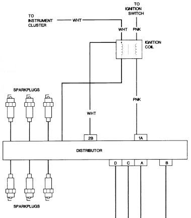
That diagram doesnt make sense. Even assuming it's HEI distributor.
The primary of a coil has either +8 or +12 volts into one conn, the other side goes to the ign module or points if it's older. Pull the leads to coil and see which has the pos voltage on it with ign key on. That will be the power input to the coil.
Ground the other connector. That would be the same side as seen going to the tach in the inst panel.
The secondary of the coil you dont have to worry about, long as it's in contact with chassis. One side goes to center pole of dist cap, the other side is frame grounded to the bracket.
Thread Starter
|
Beginning Member
Joined: Oct 2010
Posts: 19
That diagram doesnt make sense. Even assuming it's HEI distributor.
The primary of a coil has either +8 or +12 volts into one conn, the other side goes to the ign module or points if it's older. Pull the leads to coil and see which has the pos voltage on it with ign key on. That will be the power input to the coil.
Ground the other connector. That would be the same side as seen going to the tach in the inst panel.
The secondary of the coil you dont have to worry about, long as it's in contact with chassis. One side goes to center pole of dist cap, the other side is frame grounded to the bracket.
The primary of a coil has either +8 or +12 volts into one conn, the other side goes to the ign module or points if it's older. Pull the leads to coil and see which has the pos voltage on it with ign key on. That will be the power input to the coil.
Ground the other connector. That would be the same side as seen going to the tach in the inst panel.
The secondary of the coil you dont have to worry about, long as it's in contact with chassis. One side goes to center pole of dist cap, the other side is frame grounded to the bracket.
Ok I understand what your saying. But the diagram that I posted is a cut and paste from the full wiring diagram The only thing I can figure out using the diagram is that when the ignition is on the (PNK) wire is hot going to the coil and then thru the coil (+12V)to the (PNK) wiring going to the Distributor to pin #1A and then out of the distributor on pin 2B (+12V) to the coil on the (White) wire and connecting to the (White) wire inside the coil and then the (White) wire that says to Instrument Cluster is the one going to the tech and then the unmarked wire is the one going to the center pole on the dist cap Would you say this is correct? And if so How would I triger it to fire?
Starting Member
Joined: Jul 2010
Posts: 123
Here's a step by step to check the coil & ignition mod on a GM 4.3, 5.0. & 5.7 engine.
Part 1 -Ignition Control Module (ICM) Test: GM 4.3L, 5.0L, 5.7L.
You can also go to You Tube, plenty of vids on testing a coil using a spark tester.
Part 1 -Ignition Control Module (ICM) Test: GM 4.3L, 5.0L, 5.7L.
You can also go to You Tube, plenty of vids on testing a coil using a spark tester.

