NVG233 (RPO NP1) 4WD Transfer Case Info (2001 Blazer)
#1
This info is for reading diagnostic codes on the NVG233 (RPO NP1) 3-button Transfer Case System Only
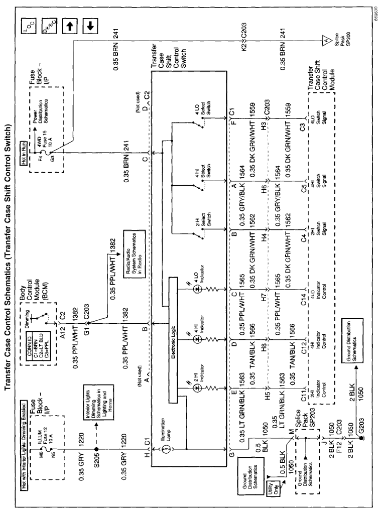
The diagnostic trouble codes are displayed on the three transfer case shift select buttons. The shift select buttons are located on the instrument panel when the on the data link cable is grounded, and the ignition switch has been OFF for at least five seconds prior to positioning the ignition switch to run the shift select buttons will blink various times together in order to indicate a diagnostic trouble code from 1 to 4.
a. Position the ignition switch to OFF. Ensure the ignition switch is positioned to OFF for at least 6 seconds.
b. Connect pin 13 on the data link connector to a vehicle ground source. The data link connector is located in the cab under the instrument panel on the drivers side.
c. Position the ignition switch to RUN.
d. Note the shift select buttons for blinking codes.
If the shift select buttons all blink one time and stop, and do not continue to blink, no fault codes are stored in the TCCM.
The transfer case shift select buttons will blink in order to identify any stored DTC. If only one code is stored in the TCCM memory, that code will blink repeatedly with a three second delay between blinking sequences. If more than one code is stored, the first code will blink once, then after a three seconds delay, the next code will blink. This sequence will continue until pin 13 is no longer grounded.
When reading the diagnostic trouble codes, the number of shift select buttons blinks will indicate the code number.
This procedure will only work with the NVG 233 NP1 Two-Speed Selectable New Venture Gear transfer case. If you have the NVG 236/246-NP8 Two-Speed Automatic New Venture Gear you will have to use a scan tool to access the DTC's.
Last edited by LesMyer; 04-27-2015 at 08:27 PM.
#6
Diagnostic Trouble Code (DTC) Clearing
The transfer case shift control module is equipped with the ability to store diagnostic information, which is useful to a technician in the event of a module component or wiring failure. This information (Diagnostic Trouble Codes (DTCs) ) should not be cleared from the transfer case shift control module until these codes have been recorded or servicing the system has lead you to a repair and directed you to perform the "Clearing Flash Codes" operation. The following steps provide an easy way of clearing the flash codes properly in the event that a fault has set improperly (due to the disconnection of the transfer case shift control module or related components) or a repair has been made to the transfer case system.
The transfer case shift control module is equipped with the ability to store diagnostic information, which is useful to a technician in the event of a module component or wiring failure. This information (Diagnostic Trouble Codes (DTCs) ) should not be cleared from the transfer case shift control module until these codes have been recorded or servicing the system has lead you to a repair and directed you to perform the "Clearing Flash Codes" operation. The following steps provide an easy way of clearing the flash codes properly in the event that a fault has set improperly (due to the disconnection of the transfer case shift control module or related components) or a repair has been made to the transfer case system.
- Turn OFF the ignition.
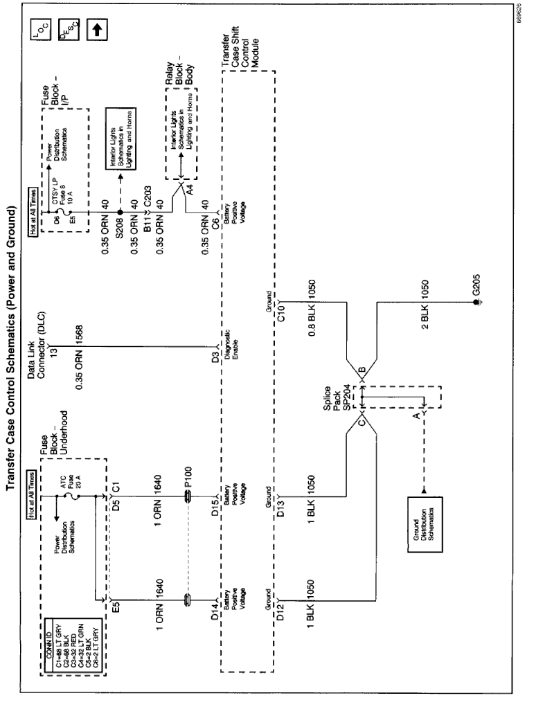
- Remove the 10 amp CTSY LP fuse from the IP fuse block.
- Wait a minimum of 60 seconds before replacing the fuse. Once the fuse is replaced DTC 1 will be set in the transfer case shift control module.
- Cycle the ignition switch from the OFF position to the RUN and back OFF five times in order to clear DTC 1 from the transfer case shift control module memory.
- Verify that the DTCs have all been cleared. Refer to Diagnostic Trouble Code (DTC) Displaying.
Last edited by LesMyer; 04-28-2015 at 10:43 AM.
#7
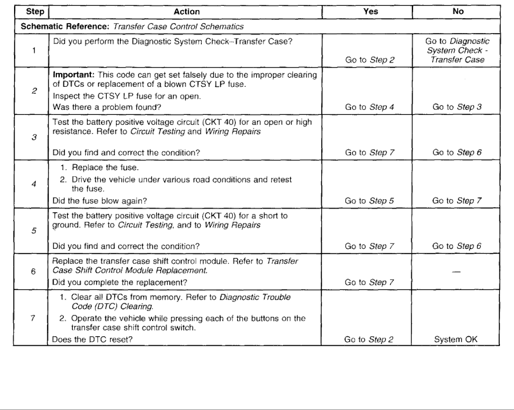
DTC 1-RAM Standby Power Loss
Circuit Description
The transfer case shift-control module normally has battery voltage supplied through the battery positive voltage circuit (CKT 40) at all times. When the ignition is ON, the transfer case shift control module conducts a self-test. This self-test determines if the current memory is the same memory that was retained when the ignition was last turned OFF. This self-test indicates whether the RAM standby power-supply to the transfer case shift control module pin C6 was interrupted. If the power is interrupted, the DTCs would be cleared from memory. If the self-test fails, the transfer case shift-control module sets DTC 1.
Conditions for Clearing the DTC
This DTC will clear when the voltage supply failure has been corrected and the ignition switch has been cycled 5 times
Test Description
The numbers below refer to the step numbers on the diagnostic table.
- This step inspects the CTSY LP fuse for an open.
- This step test the battery positive voltage circuit (CKT 40) for an open or high resistance.
- This step rechecks the CTSY LP fuse for an open.
- This step tests the battery positive voltage circuit (CKT 40) for a short to ground.
Last edited by LesMyer; 04-28-2015 at 10:43 AM.
#8
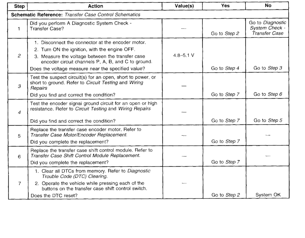
Circuit Description
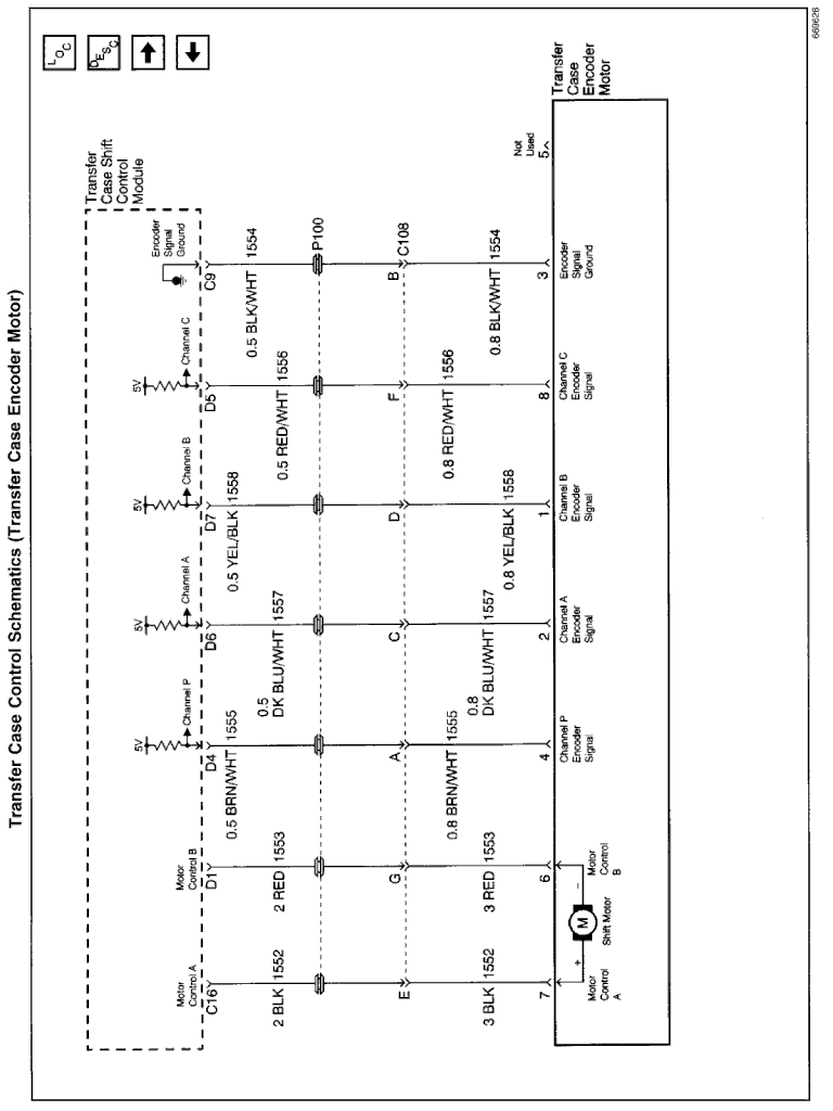
The transfer case encoder motor is an assembly which houses 4 separate channels. These channels are used to indicate to the transfer case shift control module the present gear position of the transfer case or if the transfer case is in transition between gears. The encoder motor assembly consists of an electronically conductive inner ground ring in contact with a 3 legged wiper arm. Each leg's length is such that it makes contact with the conductive regions of the 4 channels. When any leg of the wiper arm is making contact with the conductive area of any channel, the encoder provides a path to ground to the inner ground ring.
During electronic shifting, the transfer case shift control module monitors the transfer case encoder circuit for the proper operating sequence. If at any time during a shift, the encoder changes from one position to any position other than the next possible position, an error counter in the transfer case shift control module increments by 4. After the counter reaches 32, the transfer case shift control module set a DTC 2, a permanent "encoder fault," and reverts to a 2HI to 4LO or a 4LO to 2HI shift pattern only. To guard against a transient, random encoder fault due to vibration, dirt, electrical noise, etc., the fault counter reduces by one each time the transfer case shift control module detects a valid encoder value. The encoder must intermittently fail 25 percent of the time for the transfer case shift control module to consider it faulty and store DTC 2.
Conditions for Clearing the DTC
The condition for setting the DTC is no longer present and a momentary loss of battery power at the battery positive voltage circuit (CKT 40).
Test Description
The numbers below refer to the step numbers on the diagnostic table.
- This step measures the voltage between the transfer case encoder circuit channels P, A, B, and C to ground.
- This step tests the suspect circuit(s) for an open, short to power, or short to ground.
- This step tests the encoder signal ground circuit for an open or high resistance.
Last edited by LesMyer; 04-28-2015 at 10:45 AM.
#9

Circuit Description
The transfer case encoder motor has a bi-directional, permanent magnet, D.C. motor. When energized, (through Motor Control A or Motor Control B, the ground is provided by the opposing motor control circuit and then grounded through the transfer case shift control module ground circuit), the motor, through a series of gears, rotates a shaft which moves the mode and range forks to shift the transfer case between 4H, 2HI, and 4L ranges.
This DTC detects a short or open in the battery positive voltage circuit (CKT 1640), ground circuit, an internal short in the motor windings and related circuitry, or an internal transfer case shift control module failure.
Action Taken When the DTC Sets
In the event that one of the motor control circuits is energized (battery voltage is applied) the transfer case shift control module will energize the other motor control circuit to keep the motor from running.
All switch indicator lamps will flash continuously to prompt the driver that service is required. The transfer case system will be disabled and the transfer case shift control module will remain energized even with the ignition in the OFF position.
Conditions for Clearing the DTC
The condition for setting the DTC is no longer present and a momentary loss of battery power at the battery positive voltage circuit (CKT 40).
Test Description
The numbers below refer to the step numbers on the diagnostic table.
- This step tests the battery positive voltage circuit (CKT 1640) for an open or high resistance.
- This step inspects the ATC fuse for an open.
- This step tests the ground circuit.
- This step tests the Motor Control A and B circuits.
Last edited by LesMyer; 04-28-2015 at 10:46 AM.
#10

DTC 4-RAM/ROM Failure
Circuit Description
At each power up the transfer case shift control module runs a self test on the following:
- EEPROM Checksum
- ROM Checksum
- RAM Checksum
- RAM Malfunction
- Critical operational parameters stored in EEPROM have failed Checksum test indicating invalid data.
- Masked ROM code has failed Checksum test indicating that masked ROM data is not valid.
- ROM code has failed Checksum test indicating that ROM data is not valid.
- One or more ROM locations have failed operational test indicating that some portions of RAM are not functional.
The condition for setting the DTC is not present and a momentary loss of battery power at the battery positive voltage circuit (CKT 40).
Diagnostic Aids
Test Description
The numbers below refer to the step numbers on the diagnostic table.
- This step replaces the transfer case shift control module.
Last edited by LesMyer; 04-28-2015 at 10:46 AM.


