
New LED light idea

I was not speaking on his behalf, I was just saying in general when people use these high powered LED, most of them use buckpucks.
But he is using a constant current/voltage driver, Which one he is using I am not sure.
But he is using a constant current/voltage driver, Which one he is using I am not sure.

Junior Member
Joined: Apr 2016
Posts: 325
From: North GA, USA

I'm sorry, I was confused. I thought the comment I was responding to was from thogert.
I see there are also "flex block" drivers that can step up the voltage to as much as 36V in addition to supplying constant current. I'm wondering if that's necessary for this LED unit.
I see there are also "flex block" drivers that can step up the voltage to as much as 36V in addition to supplying constant current. I'm wondering if that's necessary for this LED unit.
Honestly currently I am using a Chinese Boost driver. I have been looking into circuit diagrams for how to build them and it is difficult to say the least. Converting AC to a higher voltage is easy, however to boost DC, you must create some sort of oscillating wave to put through a transformer, then rectify it. Kind of a pain really but if I ever make this a product you can bet I'll have a custom solution built for it as China is great for prototyping, but not for long term use. The reason for the odd driver and not a regular buckpuck is that this is a very unique LED, not something anyone uses for something other than high bay lighting and grow lights. So finding parts that work for this, and even finding the LED itself is difficult.
The boost driver I am using is capable of boosting up to 48VDC at up to 8 amps. This LED draws 130W measured across the led using this boost driver, which comes out to about 11 amps incoming plus whatever efficiency losses you get through the driver. So when I build something, it'll have some beefy components to be able to oscillate at least 16VDC at a decent Hz and at least 15 Amps.
The LED is actually over 100 individual LEDs in series and parallel lines inside the chip. Each one is rated at about 1W which gives it it's forward voltage and current. 36V to 38V is typical for several parallel strings of 10 LEDs in series. Here's a pic running at a voltage just high enough to kick the leds on, without activating the phosphor around them.

The actual values I'm running this LED at are 38V at 3.5A
Here's the ghetto rigged setup I'm playing with currently.

The boost driver I am using is capable of boosting up to 48VDC at up to 8 amps. This LED draws 130W measured across the led using this boost driver, which comes out to about 11 amps incoming plus whatever efficiency losses you get through the driver. So when I build something, it'll have some beefy components to be able to oscillate at least 16VDC at a decent Hz and at least 15 Amps.
The LED is actually over 100 individual LEDs in series and parallel lines inside the chip. Each one is rated at about 1W which gives it it's forward voltage and current. 36V to 38V is typical for several parallel strings of 10 LEDs in series. Here's a pic running at a voltage just high enough to kick the leds on, without activating the phosphor around them.
The actual values I'm running this LED at are 38V at 3.5A
Here's the ghetto rigged setup I'm playing with currently.
Last edited by Thogert; Jul 24, 2016 at 10:51 PM.
Junior Member
Joined: Apr 2016
Posts: 325
From: North GA, USA
thogert, If I'm reading the data sheet you linked to correctly, the maximum current for that unit is 2.8 Amps. The forward voltage measurement shown on the sheet was measured at 1.9A current at 85C temperature. Personallly, I wouldn't try to run more than 1.4A through that unit without a thermal sensing driver circuit, with a sensor on the heatsink and feedback circuitry that cuts current at higher temps, to establish equilibrium.
Ok, take a 100W incandescent, and add 30% more heat.  For an idea, here's the heatsink I'm thinking of using.

Noctua NH-C14S It's got a 140mm fan on it and supposedly can handle up to 150W of dissipation
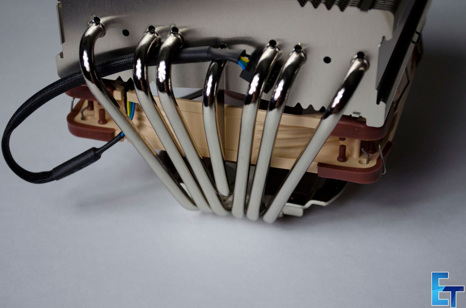
7 heatpipes of goodness and the ability to add another fan if needed. Of course the fan is only for when the truck isn't moving very fast but still. I'll pick up a Noctua NF-A14 iPPC-2000 IP67 fan to go with it for waterproofiness.
For an idea, here's the heatsink I'm thinking of using.Noctua NH-C14S It's got a 140mm fan on it and supposedly can handle up to 150W of dissipation
7 heatpipes of goodness and the ability to add another fan if needed. Of course the fan is only for when the truck isn't moving very fast but still. I'll pick up a Noctua NF-A14 iPPC-2000 IP67 fan to go with it for waterproofiness.

thogert, If I'm reading the data sheet you linked to correctly, the maximum current for that unit is 2.8 Amps. The forward voltage measurement shown on the sheet was measured at 1.9A current at 85C temperature. Personallly, I wouldn't try to run more than 1.4A through that unit without a thermal sensing driver circuit, with a sensor on the heatsink and feedback circuitry that cuts current at higher temps, to establish equilibrium.
The specs I'm testing at are of course the maximum listed as well. So perhaps I'll have to downgrade them if I ever sell them, but until then we need stress tests right?
 I can watch and tell when an LED is crying and needs a break, a slight shift in brightness and color which is pretty easy to see at these levels, but I wouldn't expect anyone buying one to watch for that.
Last edited by Thogert; Jul 26, 2016 at 11:20 PM.

Thread
Thread Starter
Forum
Replies
Last Post
96jimmyslt4x4
Lighting & Electrical
6
Sep 21, 2011 09:14 AM
96jimmyslt4x4
Lighting & Electrical
3
May 29, 2011 03:55 PM