
Voltage Gauge going nutty - Alternator Re-Wire to Voltage Reference

Thread Starter
|
New Member
Joined: Aug 2010
Posts: 63
From: Washington Twp, Mi

So I was sitting at a light with the turn signal on and happened to notice that the voltage gauge was swinging from two notches about center (assuming around 14 volts) to center (12 volts) and the only thing other than the turn signal running was the car. No radio nothing. Took it to the auto store (Orielly's) and had them check the alternator and battery. Said everything was fine. Battery is good, cause I can stick it in my camaro with a 10.5 compression ratio and it kicks the starter over no problem. The Blazer starts no problem so I dont think its the starter on it.
Is it possible that the alternator is still actually dying. I plan to replace it with a powermaster ad244 cause I have a system going in, but I figured I should figure this out first in case its not the alternator.
Also could a borderline alternator cause a P0410 code or a C0265. I have gone through the checks for both of those and still cant find the reason they keep coming on. The air pump, check valves, fuse and relay have all been replaced. The dealership has checked the ABS, all the wiring and said its all fine. They said it was the module and pump that were bad, replaced those two parts (not through the dealership though, I aint spending that kind of money on work I can do myself). Still have that code as well.

The alternators in the newer trucks are all PWM (pulse width modulated) driven for output meaning that the PCM controls the output. I have seen a number of issues just like this be caused by that PCM control lagging a bit behind demand for one reason or another.
There was a thread not too long ago detailing the procedure to rewire the alternator to be controlled by battery reference instead of by the PCM which will take it back to the old way of running an alternator that always worked!
There was a thread not too long ago detailing the procedure to rewire the alternator to be controlled by battery reference instead of by the PCM which will take it back to the old way of running an alternator that always worked!
Senior Member
Joined: Nov 2007
Posts: 689
From: Manitoba, Canada
hmm, with my signal on can just see the voltage needle move just a tad, nothing thats ever worried me to much. Just replaced the alternator again with the second one on warranty. colder than -15 and the alternator puts out funky voltage (only when rev<2000). voltage just drops down to 9 then back up to 14...does it until everythings all nice and warmed up, last winter did this threw the new alternator in and fixed it, threw another new one in today off warranty and so far its good, always thought maybe the belt was slipping in the cold a bit. If this one acts up think ill find that thread on re-wiring the alternator and see if that curbs the problem!

Thread Starter
|
New Member
Joined: Aug 2010
Posts: 63
From: Washington Twp, Mi
1. Disconnect the negative battery cable from the battery/batteries.
2. Slide the protective boot on the generator BAT terminal aside and remove the retainer and wire cable from the BAT terminal.
3. Unplug the generator 4-cavity terminal from the top of the generator.
4. Inspect cavity D on the generator connector for a red cavity plug. If a red cavity plug is present, it is not necessary to replace the generator connector. Remove the CPA and save. Remove the red cavity plug and continue with step 9. If a red cavity plug is NOT present, continue with the next step.
5. Remove and save the orange Weatherpack seal and CPA from the 4-way connector.
6. Using the proper terminal removal tool, remove the two or three wires from the 4-way connector. On vehicles without Supplemental Brake Assist (SBA), install a red cavity plug, P/N 12059168, into cavity "A" of the new 4-way connector, P/N 12186568. On some 2003 and 2004 model year vehicles with SBA, install the dark blue (Circuit 5668) wire of the vehicle wiring harness into cavity "A" of the new 4-way connector.
7. Depending on the vehicles model and year, install the brown wire (Circuit 25) or red wire (Circuit 225) of the vehicles wiring harness into cavity "B" of the new 4-way connector.
8. Install the gray (Circuit 23) wire of the vehicle wiring harness into cavity "C" of the new 4-way connector.
9. Obtain a piece of 0.80 mm/18GA black wire, 254 mm (8 in) long.
10. Install a red terminal seal, P/N 12048086, and terminal, P/N 12048074, (crimp and solder) on one end of the new black wire.
11. Install the new black wire into cavity "D" of the new 4-way connector.
12. Reinstall the connector seal and CPA, from the original connector, to the new connector.
13. Plug the 4-way connector into the generator.
14. Route the black wire to the generator BAT terminal, sliding the wire into the small end to the output terminal boot, along side the generator output wire.
15. Obtain a ring terminal from the terminal kit (J-38125-D) that is the same diameter as the positive post of the generator. Crimp and solder the ring terminal from the terminal kit (J-38125-D) on to the open end of the new black wire.
16. Place the generator output wire and the new black wire onto the generator BAT terminal and install the retainer.
17. Connect the negative battery cable.
Note: This modification will not work if the vehicle is utilizing the new "Regulated Voltage Control" system. This is new feature on some full-size trucks and utilities for the 2005 model year. Please inspect the vehicle prior to performing this modification.
Please follow this diagnostic or repair process thoroughly and complete each step. If the condition exhibited is resolved without completing every step, the remaining steps do not need to be performed.
Also, instead of spending 40+ at a dealership for the pigtail, or 20 bucks through RockAuto I found a place that you can buy the individual parts of the connector for, actually they carry alot of the different connectors used by GM. I got all the parts needed to do this conversion for 12 bucks shipped to my house. I just will reuse the two wires in there (small paperclip works well as an extraction tool)
1 -- red cavity plug, P/N 12059168 $0.16ea
1 -- 4-way connector, P/N 12186568 $1.93ea
5 -- red terminal seal, P/N 12048086 (5 is the min. you can get) $0.14ea
5 -- terminal, P/N 12048074 (5 is the min. you can get) $0.19ea
http://www.pcsconnectors.com/
Last edited by 2001Blue; Dec 22, 2010 at 10:09 AM. Reason: Making the steps easier to distinguish
I've used PCSConnectors.com in the past. Good source for sometimes obscure stuff.
If you go through this and have time to snap some pictures and do a writeup, please post it in the Article Submission/Discussion subsection within the Tech Article (DIY) section.
If you go through this and have time to snap some pictures and do a writeup, please post it in the Article Submission/Discussion subsection within the Tech Article (DIY) section.
Thread Starter
|
New Member
Joined: Aug 2010
Posts: 63
From: Washington Twp, Mi
So I got all the parts today and then realized that I left the pin that I had already crimped to a black wire (turns out my job had a few of the pins for this project there, so I didnt order any pins) and the rings terminals at my desk at work and now cant do this fix until monday.
Thread Starter
|
New Member
Joined: Aug 2010
Posts: 63
From: Washington Twp, Mi
This is how to convert your alternators voltage regulated from being PWM controlled to battery reference. I got this from zr2 forum and just added some pictures as I did for my blazer, along with some other helpful stuff like where to get the parts and tools;
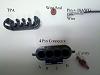
What you will need:
1/2" open end wrench for alternator stud
Wire Crimper
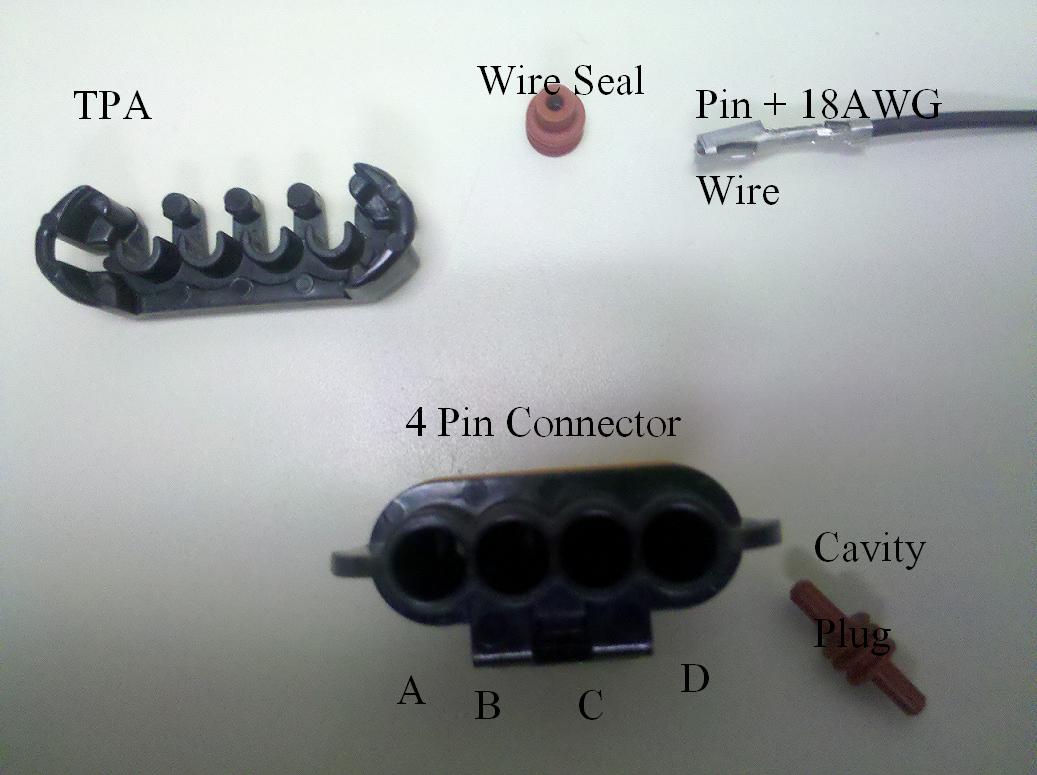
1 -- red cavity plug, P/N 12059168 $0.16ea
1 -- 4-way connector, P/N 12186568 $1.93ea
5 -- red terminal seal, P/N 12048086 (5 is the min. you can get) $0.14ea
5 -- terminal, P/N 12048074 (5 is the min. you can get) $0.19ea
(See 1st Attachment)
The site below carries these parts instead of spending 20+ through RockAuto or 40+ through a dealership
http://www.pcsconnectors.com/
1. Disconnect the negative battery cable from the battery/batteries.
2. Slide the protective boot on the generator BAT terminal aside and remove the retainer and wire cable from the BAT terminal.
3. Unplug the generator 4-cavity terminal from the top of the generator.
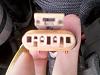
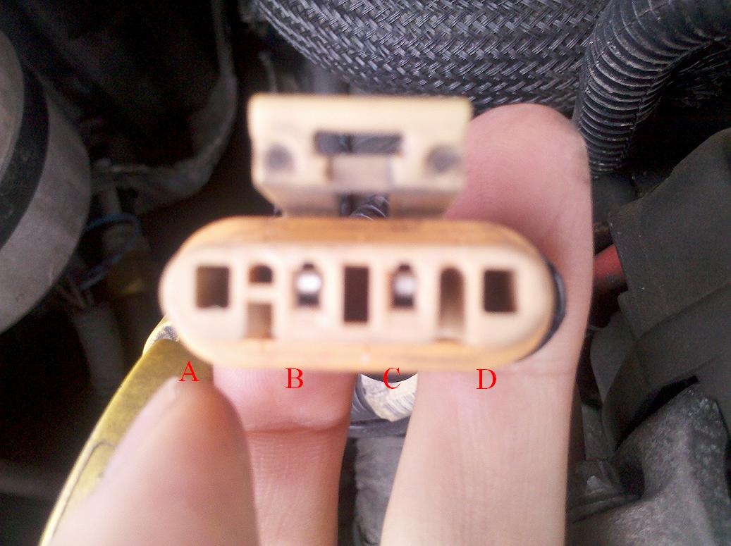
4. Inspect cavity D on the generator connector for a red cavity plug. If a red cavity plug is present, it is not necessary to replace the generator connector. Remove the CPA and save. Remove the red cavity plug and continue with step 7. If a red cavity plug is NOT present, continue with the next step. Mine didn't have a true 4 pin connector it was a molded with only 2 cavities available so I got the new connector. To be honest, they are so cheap I would buy new either way.
(See 2nd attachment)
5. Remove and save the orange Weatherpack seal and CPA from the 4-way connector. Again, I just bought all this new anyway
6. Using the proper terminal removal tool (I ended up filing down a paper clip to fit into the slot to disengaged the pins), remove the two or three wires from the 4-way connector. On vehicles without Supplemental Brake Assist (SBA), install a red cavity plug into cavity "A" of the new 4-way connector. On some 2003 and 2004 model year vehicles with SBA, install the dark blue (Circuit 5668) wire of the vehicle wiring harness into cavity "A" of the new 4-way connector.
7. Obtain a piece of 0.80 mm/18GA black wire, 254 mm (8 in) long.
8. Install a red terminal seal and terminal (crimp and solder) on one end of the new black wire.
9. Install the new black wire into cavity "D" of the new 4-way connector.
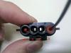
10. Depending on the vehicles model and year, install the brown wire (Circuit 25) or red wire (Circuit 225) of the vehicles wiring harness into cavity "B" of the new 4-way connector.
(See 3rd Attachment)
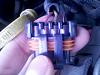
11. Install the gray (Mine had turned yellowish at the end) (Circuit 23) wire of the vehicle wiring harness into cavity "C" of the new 4-way connector.
12. Reinstall the connector seal and CPA, from the original connector, to the new connector.
(See 4th Attachment)
13. Plug the 4-way connector into the generator.
14. Route the black wire to the generator BAT terminal, sliding the wire into the small end to the output terminal boot, along side the generator output wire.
15. Obtain a ring terminal from the terminal kit (I used an 18AWG ring terminal for a 3/8" stud) that is the same diameter as the positive post of the generator. Crimp and solder the ring terminal to the open end of the new black wire.
16. Place the generator output wire and the new black wire onto the generator BAT terminal and install the retainer.
(See 5th Attachment)
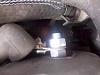
17. Connect the negative battery cable.
Note: This modification will not work if the vehicle is utilizing the new "Regulated Voltage Control" system. This is new feature on some full-size trucks and utilities for the 2005 model year. Please inspect the vehicle prior to performing this modification.
Please follow this diagnostic or repair process thoroughly and complete each step. If the condition exhibited is resolved without completing every step, the remaining steps do not need to be performed.
What you will need:
1/2" open end wrench for alternator stud
Wire Crimper
1 -- red cavity plug, P/N 12059168 $0.16ea
1 -- 4-way connector, P/N 12186568 $1.93ea
5 -- red terminal seal, P/N 12048086 (5 is the min. you can get) $0.14ea
5 -- terminal, P/N 12048074 (5 is the min. you can get) $0.19ea
(See 1st Attachment)
The site below carries these parts instead of spending 20+ through RockAuto or 40+ through a dealership
http://www.pcsconnectors.com/
1. Disconnect the negative battery cable from the battery/batteries.
2. Slide the protective boot on the generator BAT terminal aside and remove the retainer and wire cable from the BAT terminal.
3. Unplug the generator 4-cavity terminal from the top of the generator.
4. Inspect cavity D on the generator connector for a red cavity plug. If a red cavity plug is present, it is not necessary to replace the generator connector. Remove the CPA and save. Remove the red cavity plug and continue with step 7. If a red cavity plug is NOT present, continue with the next step. Mine didn't have a true 4 pin connector it was a molded with only 2 cavities available so I got the new connector. To be honest, they are so cheap I would buy new either way.
(See 2nd attachment)
5. Remove and save the orange Weatherpack seal and CPA from the 4-way connector. Again, I just bought all this new anyway
6. Using the proper terminal removal tool (I ended up filing down a paper clip to fit into the slot to disengaged the pins), remove the two or three wires from the 4-way connector. On vehicles without Supplemental Brake Assist (SBA), install a red cavity plug into cavity "A" of the new 4-way connector. On some 2003 and 2004 model year vehicles with SBA, install the dark blue (Circuit 5668) wire of the vehicle wiring harness into cavity "A" of the new 4-way connector.
7. Obtain a piece of 0.80 mm/18GA black wire, 254 mm (8 in) long.
8. Install a red terminal seal and terminal (crimp and solder) on one end of the new black wire.
9. Install the new black wire into cavity "D" of the new 4-way connector.
10. Depending on the vehicles model and year, install the brown wire (Circuit 25) or red wire (Circuit 225) of the vehicles wiring harness into cavity "B" of the new 4-way connector.
(See 3rd Attachment)

11. Install the gray (Mine had turned yellowish at the end) (Circuit 23) wire of the vehicle wiring harness into cavity "C" of the new 4-way connector.
12. Reinstall the connector seal and CPA, from the original connector, to the new connector.
(See 4th Attachment)

13. Plug the 4-way connector into the generator.
14. Route the black wire to the generator BAT terminal, sliding the wire into the small end to the output terminal boot, along side the generator output wire.
15. Obtain a ring terminal from the terminal kit (I used an 18AWG ring terminal for a 3/8" stud) that is the same diameter as the positive post of the generator. Crimp and solder the ring terminal to the open end of the new black wire.
16. Place the generator output wire and the new black wire onto the generator BAT terminal and install the retainer.
(See 5th Attachment)

17. Connect the negative battery cable.
Note: This modification will not work if the vehicle is utilizing the new "Regulated Voltage Control" system. This is new feature on some full-size trucks and utilities for the 2005 model year. Please inspect the vehicle prior to performing this modification.
Please follow this diagnostic or repair process thoroughly and complete each step. If the condition exhibited is resolved without completing every step, the remaining steps do not need to be performed.
Last edited by swartlkk; Dec 28, 2010 at 11:55 AM. Reason: added attached images & auto thumbs to the post in the proper locations