2003 4 door 4x4 Blazer
#21
the pump was not connected when i got those readings. But during this whole process i never once heard it prime.
#23
Repeated with it connected and im getting extremely low voltage while testing power but still good resistance.
#24
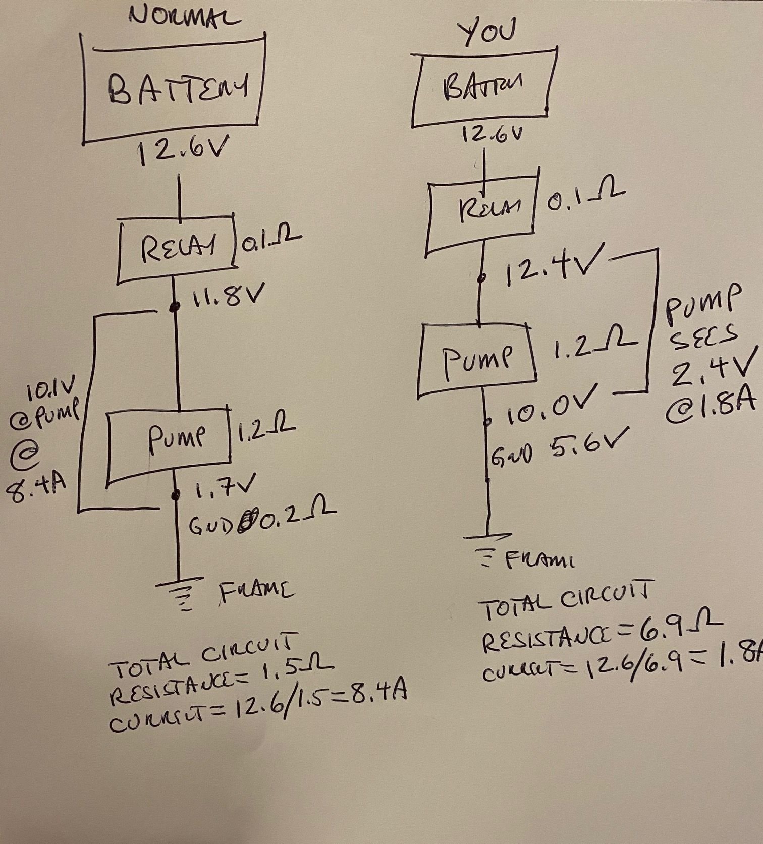
Now we are getting somewhere. This is why you have to test the circuit under a load because it reveals the full impact of any wiring/corrosion issues. If your ground wire resistance is accurate then this may be your problem and here is why:
Volts = current x resistance or V=IR, ohms law. Lets say the pump is supposed to draw 10 amps of current but it can't because the ground connection is 5.6 ohms so the whole circuit draws 12v/5.6 ohms = 2.1 amps or less instead (the pump has some resistance too). That 5.6v ground connection is then a resistor divider along with the pump resistance and over half of the 12v drops across that ground circuit, lifting pump ground by many volts. This means that there is a massive voltage drop likely occurring in the ground circuit and the net voltage available to the pump is near zero. Here is how you test it. Pump attached so full load on the circuit. Grind a really shiny clean spot on the frame (no sparks) and measure the voltage between the back probed black ground wire at the pump connector and the shiny frame ground. That voltage drop should be a fraction of a volt. I bet its many volts instead. Your pump ground is not ground. This is during a prime attempt at key on. Also measure the voltage from the gray power wire at the connector and the shiny frame ground. I'll bet its near 12V still.
If I am right and this confirms then you need to repair or make a new ground.
George
#27

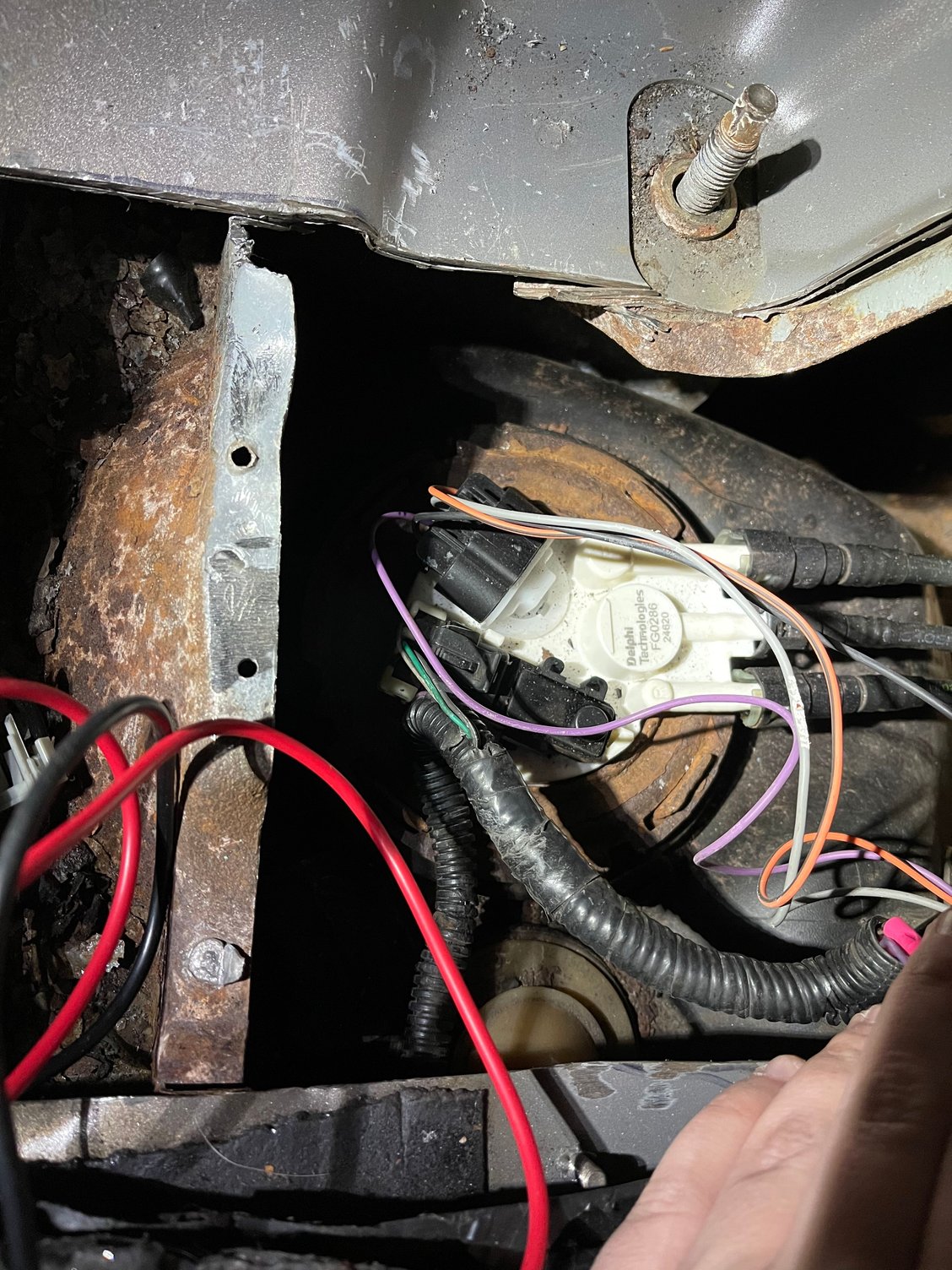
On the left side is the frame piece i gridded down and i was putting my negative lead to.
#29
next i did positive lead to back probe of grey wire and black lead to shiny metal. Results were also in mili volts. Around 20 mVDC.
my current thought process is that the piece i am using is not a good ground or i was not able to accurately get a read on the wiring.
#30
Try this. black meter probe to shiny frame metal, red meter probe to gray wire at the connector, connector removed from pump, meter on 20vdc scale, measure during 2 second prime.
Repeat with connector attached to the pump.
George
,
Repeat with connector attached to the pump.
George
,


