NP8 Auto 4WD Transfer Case Info (2001 Blazer)
#1
I'm in process of diagnosing mine and I came across this and thought it was great help - so here it is for everyone to use.
Transfer Case Description and Operation
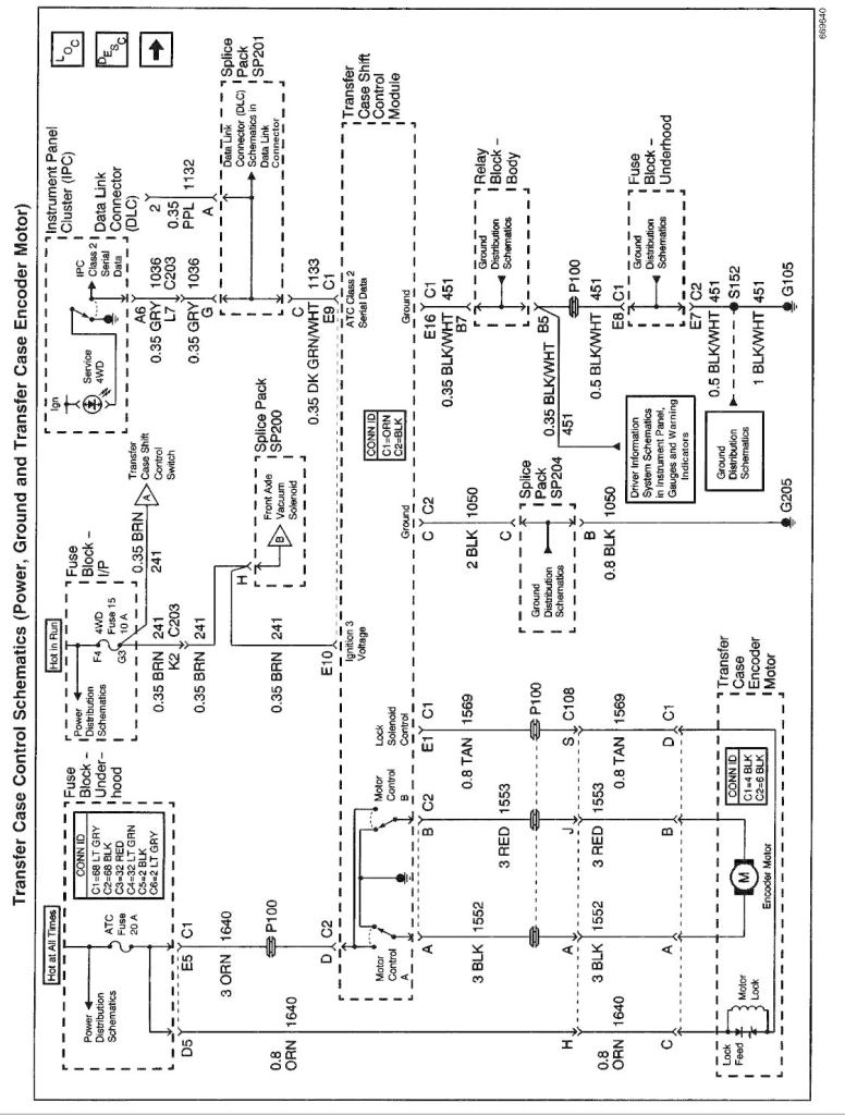
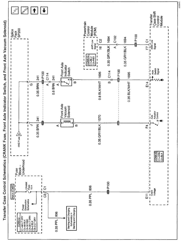
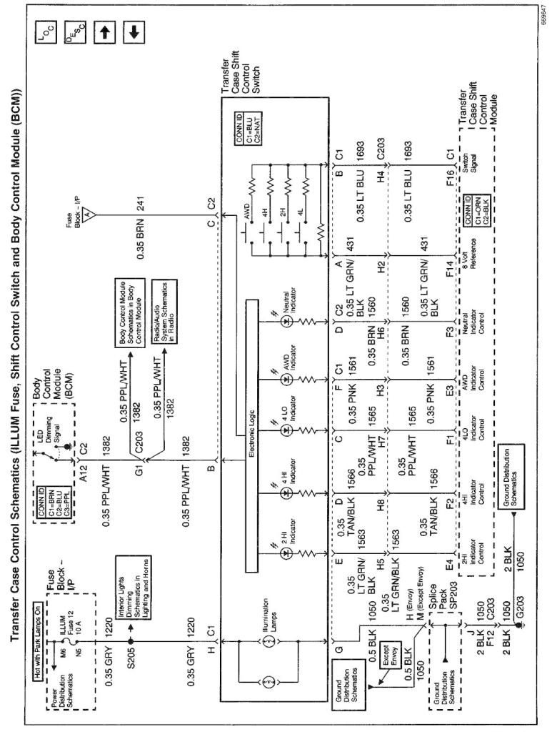
The NVG 236/246 transfer case features a 4 button shift control switch located on the instrument panel. When the vehicle has the ignition key in the RUN position, the transfer case shift control module starts monitoring the Transfer case shift control switch to determine if the driver desires a new mode/gear position. At a single press of the transfer case shift control switch, the lamp of the new desired position will begin flashing to inform the driver that the transfer case shift control module has received the request for a new mode/gear position. The lamp will continue to flash until all shifting criteria has been met and the new mode/gear position has been reached (or has been engaged). Once the new mode/ gear position is fully active, the switch indicator lamp for the new position will remain ON constantly. During normal driving situations the transfer case can operate in the Auto 4WD mode. In the Auto 4WD mode the transfer case shift control module monitors rear wheel slip speed (based on the inputs from both the front and rear propshaft speed sensors). When the vehicle experiences a rear wheel slip condition, the transfer case shift control module sends a Pulse Width Modulated (PWM) signal to an electronic motor (transfer case encoder motor). This motor rotates the transfer case sector shaft, applying a clutch pack. This clutch pack is designed to deliver a variable amount of torque (normally delivered to the rear wheels) and transfers it to the front wheels. Torque is then ramped up to the front wheels until the front propshaft speed sensor matches that of the rear propshaft speed sensor. Torque is then ramped down until torque is completely removed from the front wheels or until rear wheel slip is once again detected (the process would then repeat). The NVG 236/246 transfer case has the added feature of also providing the driver with 3 manual mode/gear positions:
Transfer Case Shift Control Module
The transfer case shift control module uses the VIN information for calculations that are required for the different calibrations used based on axle ratio, transmission, tire size, and engine. The system does not know which calibration to use without this information. This information is provided to the transfer case shift control module via Class 2 data bus from the Powertrain Control Module (PCM).
The transfer case shift control module monitors front and rear propshaft speed as well as controlling the operation of the transfer case encoder motor assembly and the engaging and disengaging of the front axle.
Transfer Case Encoder Motor
The transfer case encoder motor consists of a Permanent Magnet (PM) DC motor and gear reduction assembly. It is located on the left hand side of the transfer case. When activated it turns the sector shaft of the transfer case (clockwise or counter clockwise) to shift the transfer case and to apply the clutch that applies the front propshaft. The encoder motor is controlled with a Pulse Width Modulated (PWM) circuit provided by the transfer case shift control module. This circuit consists of a driver on both the Motor Control A and Motor Control B circuits. The encoder motor is bi-directional to allow the motor to shift the transfer case from 2HI or 4HI to NEUTRAL and 4LO positions.
The transfer case encoder motor can be turned ON and OFF using a scan tool. You may also monitor Motor Control A and B circuits using a scan tool.
Transfer Case Encoder
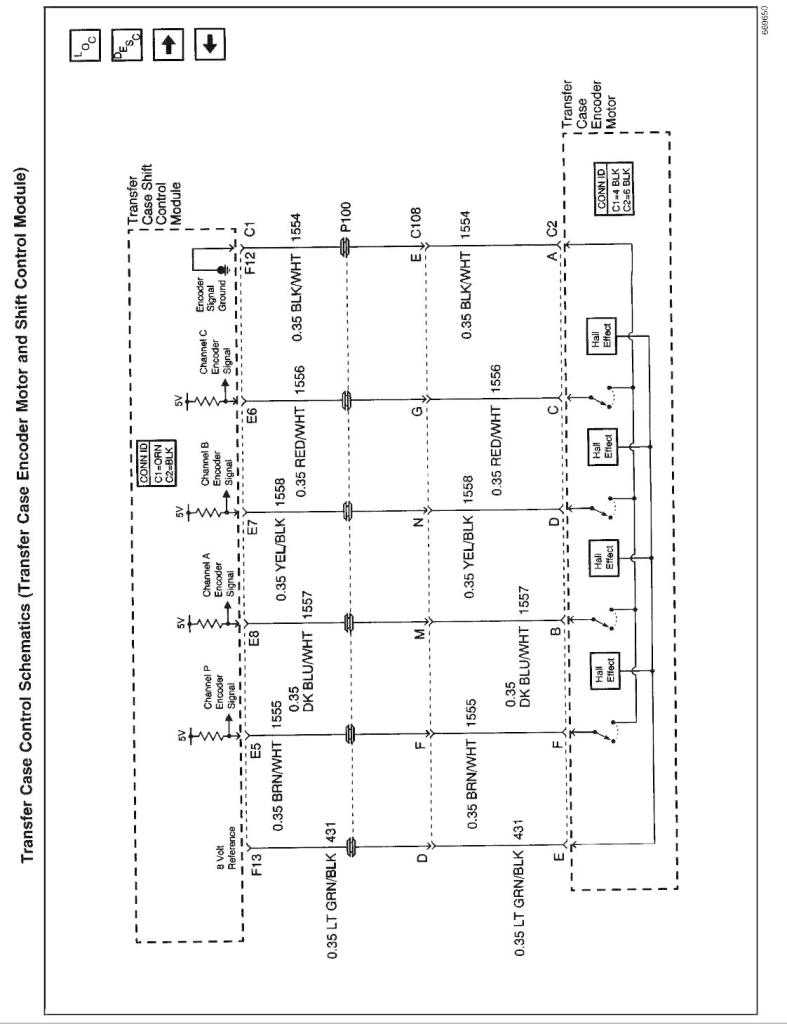
The encoder is mounted to the transfer case encoder motor assembly and is replaced only as an assembly. The encoder converts the sector shaft position (representing a mode or range) into electrical signal inputs to the transfer case shift control module. The module detects what position the transfer case is in by monitoring the 4 encoder channels (P. A,B, and C). These inputs translate into AUTO 4WD, 2HI, 4HI, NEUTRAL, and 4LO or whether the motor is still in transition between gears.
The transfer case encoder channel circuits may be monitored using a scan tool.
Transfer Case Motor Lock
The transfer case motor lock is used to prevent the transfer case from changing mode/gear positions or popping out of position when the vehicle is in 2HI, 4HI, and 4LO. When the lock circuit is energized, the transfer case encoder motor is allowed to rotate. When the transfer case is placed PHI, 4HI, or 4LO the motor lock circuit has no voltage provided to it (applying the lock) which assures that the transfer case remains in the current mode/gear position. When AUTO 4WD is selected the motor lock remains applied until an adaptive mode (torque is applied to the front propshaft) is required. During an adaptive mode the motor lock circuit is energized (locking mechanism is released), enabling the encoder motor to turn and apply torque to the front propshaft.
The transfer case motor lock circuit can be turned ON and OFF using a scan tool. You may also monitor the lock circuit using a scan tool.
Transfer Case Speed Sensors
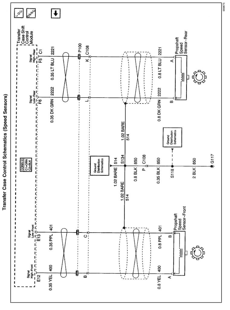
There are three speed sensors mounted on the transfer case, two on the rear output shaft and one on the front output shaft. Each speed sensor is a Permanent Magnet (PM) generator. The PM generator produces a AC voltage. The AC voltage level and number of pulses increases as speed increases.
Vehicle Speed Sensor
One of the two speed sensors on the rear output shaft is the Vehicle Speed Sensor (VSS) input to the Powertrain Control Module (PCM) . The PCM sends this information to the transfer case shift control module via the Class 2 serial data bus.
Rear Propshaft Speed Sensor
The transfer case shift control module converts the pulsating AC voltage from the rear transfer case speed sensor to a rear propshaft speed in RPM to be used for calculations. The rear propshaft speed can be displayed with a scan tool.
Front Propshaft Speed Sensor
The transfer case shift control module converts the pulsating AC voltage from the front transfer case speed sensor to front propshaft speed in RPM to be used for calculations, and to monitor the difference between the front and rear sensor speed. It is also used in the AUTO 4WD mode to determine the amount of slip and the percent of torque to apply to the front axle. The front propshaft speed can be displayed with a scan tool.
SERVICE Indicator (4WD/AWD) Lamp
The SERVICE indicator (4WD/AWD) lamp is an integral part of the cluster and cannot be serviced separately. This lamp is used to inform the driver of the vehicle of malfunctions within the Automatic Transfer Case (ATC) system. The SERVICE indicator (4WD/AWD) lamp is controlled by the transfer case shift control module via a Class 2 message or by a Service Indicator Control circuit.
Transfer Case Description and Operation
The NVG 236/246 transfer case features a 4 button shift control switch located on the instrument panel. When the vehicle has the ignition key in the RUN position, the transfer case shift control module starts monitoring the Transfer case shift control switch to determine if the driver desires a new mode/gear position. At a single press of the transfer case shift control switch, the lamp of the new desired position will begin flashing to inform the driver that the transfer case shift control module has received the request for a new mode/gear position. The lamp will continue to flash until all shifting criteria has been met and the new mode/gear position has been reached (or has been engaged). Once the new mode/ gear position is fully active, the switch indicator lamp for the new position will remain ON constantly. During normal driving situations the transfer case can operate in the Auto 4WD mode. In the Auto 4WD mode the transfer case shift control module monitors rear wheel slip speed (based on the inputs from both the front and rear propshaft speed sensors). When the vehicle experiences a rear wheel slip condition, the transfer case shift control module sends a Pulse Width Modulated (PWM) signal to an electronic motor (transfer case encoder motor). This motor rotates the transfer case sector shaft, applying a clutch pack. This clutch pack is designed to deliver a variable amount of torque (normally delivered to the rear wheels) and transfers it to the front wheels. Torque is then ramped up to the front wheels until the front propshaft speed sensor matches that of the rear propshaft speed sensor. Torque is then ramped down until torque is completely removed from the front wheels or until rear wheel slip is once again detected (the process would then repeat). The NVG 236/246 transfer case has the added feature of also providing the driver with 3 manual mode/gear positions:
- 4HI - 4 Wheel Drive high range
- 2HI - 2 Wheel Drive high range
- 4LO - 4 Wheel Drive low range The driver may choose to select any of these mode/gear positions while driving the vehicle. However, the transfer case will not allow a shift into or out of 4LO unless the following criteria has been met:
- The engine is running.
- The automatic transmission is in Neutral (clutch depressed on manual transmissions).
- The vehicle speed is below 5 km/h (3 mph) . This transfer case also has a Neutral position. A shift to the Neutral position allows the vehicle to be towed without the rear axle rotating the transfer case main shaft and the transmission output shaft. Neutral position may be obtained only if the following criteria has been met:
- The engine is running.
- The automatic transmission is in Neutral (clutch depressed on manual transmissions).
- The vehicle speed is below 5 km/h (3 mph).
- The transfer case is in 2HI mode. Once these conditions have been met, press and hold both the 2HI and 4LO buttons for 10 seconds. When the system completes the shift to neutral, the red neutral lamp will illuminate.
Transfer Case Shift Control Module
The transfer case shift control module uses the VIN information for calculations that are required for the different calibrations used based on axle ratio, transmission, tire size, and engine. The system does not know which calibration to use without this information. This information is provided to the transfer case shift control module via Class 2 data bus from the Powertrain Control Module (PCM).
The transfer case shift control module monitors front and rear propshaft speed as well as controlling the operation of the transfer case encoder motor assembly and the engaging and disengaging of the front axle.
Transfer Case Encoder Motor
The transfer case encoder motor consists of a Permanent Magnet (PM) DC motor and gear reduction assembly. It is located on the left hand side of the transfer case. When activated it turns the sector shaft of the transfer case (clockwise or counter clockwise) to shift the transfer case and to apply the clutch that applies the front propshaft. The encoder motor is controlled with a Pulse Width Modulated (PWM) circuit provided by the transfer case shift control module. This circuit consists of a driver on both the Motor Control A and Motor Control B circuits. The encoder motor is bi-directional to allow the motor to shift the transfer case from 2HI or 4HI to NEUTRAL and 4LO positions.
The transfer case encoder motor can be turned ON and OFF using a scan tool. You may also monitor Motor Control A and B circuits using a scan tool.
Transfer Case Encoder
The encoder is mounted to the transfer case encoder motor assembly and is replaced only as an assembly. The encoder converts the sector shaft position (representing a mode or range) into electrical signal inputs to the transfer case shift control module. The module detects what position the transfer case is in by monitoring the 4 encoder channels (P. A,B, and C). These inputs translate into AUTO 4WD, 2HI, 4HI, NEUTRAL, and 4LO or whether the motor is still in transition between gears.
The transfer case encoder channel circuits may be monitored using a scan tool.
Transfer Case Motor Lock
The transfer case motor lock is used to prevent the transfer case from changing mode/gear positions or popping out of position when the vehicle is in 2HI, 4HI, and 4LO. When the lock circuit is energized, the transfer case encoder motor is allowed to rotate. When the transfer case is placed PHI, 4HI, or 4LO the motor lock circuit has no voltage provided to it (applying the lock) which assures that the transfer case remains in the current mode/gear position. When AUTO 4WD is selected the motor lock remains applied until an adaptive mode (torque is applied to the front propshaft) is required. During an adaptive mode the motor lock circuit is energized (locking mechanism is released), enabling the encoder motor to turn and apply torque to the front propshaft.
The transfer case motor lock circuit can be turned ON and OFF using a scan tool. You may also monitor the lock circuit using a scan tool.
Transfer Case Speed Sensors
There are three speed sensors mounted on the transfer case, two on the rear output shaft and one on the front output shaft. Each speed sensor is a Permanent Magnet (PM) generator. The PM generator produces a AC voltage. The AC voltage level and number of pulses increases as speed increases.
Vehicle Speed Sensor
One of the two speed sensors on the rear output shaft is the Vehicle Speed Sensor (VSS) input to the Powertrain Control Module (PCM) . The PCM sends this information to the transfer case shift control module via the Class 2 serial data bus.
Rear Propshaft Speed Sensor
The transfer case shift control module converts the pulsating AC voltage from the rear transfer case speed sensor to a rear propshaft speed in RPM to be used for calculations. The rear propshaft speed can be displayed with a scan tool.
Front Propshaft Speed Sensor
The transfer case shift control module converts the pulsating AC voltage from the front transfer case speed sensor to front propshaft speed in RPM to be used for calculations, and to monitor the difference between the front and rear sensor speed. It is also used in the AUTO 4WD mode to determine the amount of slip and the percent of torque to apply to the front axle. The front propshaft speed can be displayed with a scan tool.
SERVICE Indicator (4WD/AWD) Lamp
The SERVICE indicator (4WD/AWD) lamp is an integral part of the cluster and cannot be serviced separately. This lamp is used to inform the driver of the vehicle of malfunctions within the Automatic Transfer Case (ATC) system. The SERVICE indicator (4WD/AWD) lamp is controlled by the transfer case shift control module via a Class 2 message or by a Service Indicator Control circuit.
Last edited by LesMyer; 02-28-2015 at 01:32 PM.
#3
Updating my old post with additional info......
Below is lifted from an old post by Swartlkk at 4x4 Light consistent blink while engaged. This shows the resistance that should be observed when different buttons are pressed on the contols.
-----------------------------------
For the resistance, you have to use the parallel resistance formula:

In this case, there are only two parallel resistors when only one button is pushed.
The resistance between connector 1 pins A & B are as follows for single button push:
Just for others that take a look at this thread later on, this is for the Auto4wd (NP8) NV236 transfer case shift control switch only. The NV233 (NP1) transfer case is a direct connection with dedicated wires for the different modes and is easier to test.
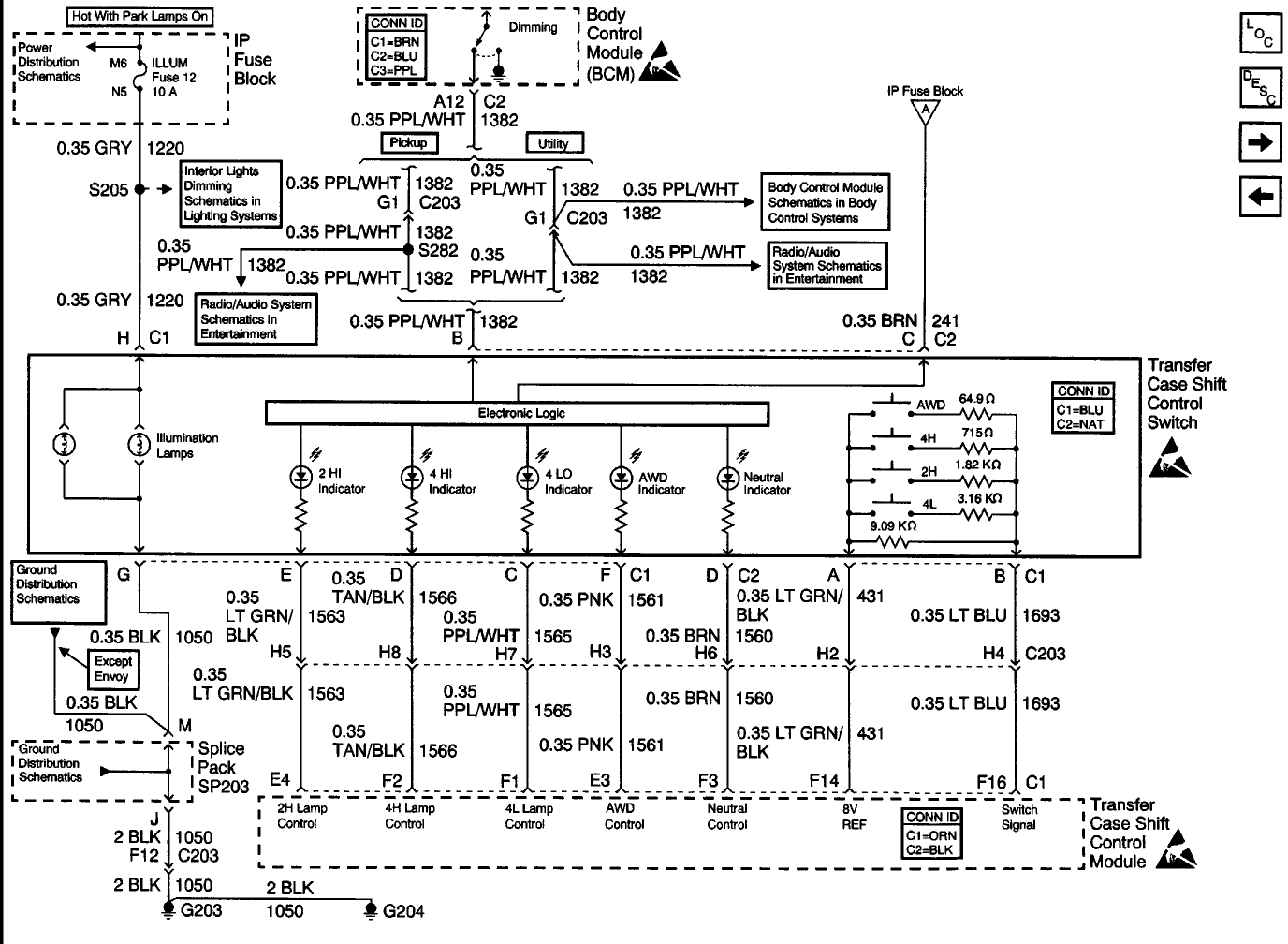
Below is lifted from an old post by Swartlkk at 4x4 Light consistent blink while engaged. This shows the resistance that should be observed when different buttons are pressed on the contols.
-----------------------------------
For the resistance, you have to use the parallel resistance formula:

In this case, there are only two parallel resistors when only one button is pushed.
The resistance between connector 1 pins A & B are as follows for single button push:
- No buttons pushed - 9.09kOhm (9090 Ohm)
- 4Low pushed - 2.345kOhm (2345 Ohm)
- 2High pushed - 1.516kOhm (1516 Ohm)
- 4High pushed - 0.663kOhm (663 Ohm)
- Auto4WD pushed - 0.064kOhm (64 Ohm)
Just for others that take a look at this thread later on, this is for the Auto4wd (NP8) NV236 transfer case shift control switch only. The NV233 (NP1) transfer case is a direct connection with dedicated wires for the different modes and is easier to test.

Last edited by LesMyer; 04-15-2015 at 08:52 AM.
#4
Here is info on using an OBD2 terminal to communicate with the TCCM to read and clear codes. This was lifted from how to read TCCM codes (4WD service light) with a $149 scanner - Chevy TrailBlazer, TrailBlazer SS and GMC Envoy Forum
I have verified that it works with my 2001 Blazer with RPO=NP8 transfer case (auto 4WD) using a Windows Notebook, Scan XL Pro software and the OBDLink interface. The OBDLink hardware comes with software included OBDWiz that should also do the job and lower the cost to only $29 but I have not tried it yet. I only used Scan XL Pro because I already had it installed. Need to be a bit of a nerd to do this in terminal mode, but it's pretty easy once you get the hang of it. Also should be able to use to communicate with other modules like ABS, etc. that are not included with the cheap scanners (once the adresses of the different modules are figured out). I have highlighted the truly pertinent info in red below. Actual codes in Blazer Code list may be slightly different, but you can easily see how to interpret what is returned by the TCCM.
-----------------------------
Good news, You can pull TCCM codes with a fairly inexpensive scanner.
NOTE that this works on our trailblazer. From all the reading i did this should work for anyone. As all with the internet, proceed at your own devices!
If you do this or expand on it (reading values from sensors etc) please let everyone know!
To do this you need a scanner which lets you send a message by manually typing in the message. There are several of these out there, no idea which is better, worse, or the same. if you have the scantool, you need software to control it. There are free versions out there, though i opted to pay to get something which works with less hassle. The scantool.net scanner with Scan XL pro SW is on sale for $149 (not sure how often they run sales, or if this is an all the time price)
I went with the ODBLink Scan Tool from scantool.net with the scanXL Pro SW with the GM package add on since we have 3 GM vehicles.
so in summary you need a computer based scanner and software that lets you send messages manually (sometimes called terminal mode)
I figured out the messages to send to get codes from the TCCM on an 02 trailblazer, should be the same for all years.
this seems complicated, though just about anyone can do this. quite frankly you can just send the messages I listed and not delve into the details of what it all means
the messages are in Hexadecimal, don't let that scare you
I started to tool, selected ODB-II->connect and followed the instructions, then selected the "tool" tab and clicked on "ODB-II terminal", select "custom send tab", check the box "enable ODB-II terminal" in the top left. now you are ready to send messages!
quick example:
with the 4WD service light on:
send message: 6C 1A F1 19 C2 ff 00
Received: $6C $F1 $1A $59 $43 $79 $93 $6A
the $43 $79 is the code, and the $93 is the status indicating the code is turning on the 4WD service light
code list:
$43 $00 = C0300
$43 $05 = C0 305
$43 $06 = C0306
$43 $21 = C0321
$43 $27 = C0327
$43 $59 = C0359
$43 $74 = C0374
$43 $79 = C0379 ***** the code indicated in the message above
$45 $50 = C0550
$87 $70 = B0770
$87 $75 = B0775
$87 $80 = B0780
$87 $85 = B0785
$87 $90 = B0790
$A7 $25 = B2725
$D3 $01 = U1301
here are the messages I figured out that seem useful:
message: 6C 1A F1 14 - turn off 4WD service light (clears codes)
message: 6C 1A F1 19 D2 ff 00 - return current and pending codes
message: 6C 1A F1 19 c2 ff 00 - returns current code
message: 6C 1A F1 19 ff ff 00 - return all code status (what I prefer)
you can stop here or get into the details:
each group of 2 below is what is called a "byte"
the address of the TCCCM is 1A
the address of the scantool is F1
$6C $1A $F1 $19 $C2 $FF $00
$GG $HH $JJ $KK $LL $MM $NN <- use these to look through the list
GG - 6C = node to node GM message
HH - 1A = address of scanner
JJ - F1 = address of TCCM
KK - 19 = what kind of request (19) Request Diagnostic Trouble Codes
by Status (14) to clear codes
LL - C2 = what data you want to get. (C2) return current codes (D2)
return current and pending codes (FF) everything
MM - FF = (FF) send to all groups (not sure why 40 chassis doesn't
work)
NN - 00 = extra padding, leave at 00
The response should be formatted as follows:
Byte1 Byte2 byte3 Byte4 Byte5 Byte6 Byte7 Byte8
sample response:
$6C $F1 $1A $59 $43 $79 $93 $6A
$PP $QQ $RR $SS $XZ $ZZ $YY $VV <- use these to look through the list
below
Byte1 - PP - 6C - same as the first byte you sent
Byte2 - QQ - F1 - address of the scan tool (indicates the recipient)
Byte3 - RR - 1A - address of the TCCM module (indicates the originator)
Byte4 - SS - 59 - will be the byte4 you sent with 40 added to it
Byte5 - XZ - 43 - first part of code
Byte6 - ZZ - 79 - second part of code
Byte7 - YY - 93 - status (01) good, no issue (93) current code causing service light to illuminate (11) not sure, seemed to be associated to the last code raised, though I'm not sure
Byte8 - VV - 6A - check sum (ignore this, it is used to make sure the message made it without loosing data)
so bytes 4 and 5 have the code, to decipher:
$43 $79 <- from recceived message
$XZ $ZZ <- use this to decode based on the list below
the X is the first part of the code
4 = C0
8 = B0
A = B2
D = U1
ZZZ = code
for complete code put together XZZZ
so the $43 $79 is:
4 = C0
ZZZ = 379
code = C0379
if you get 00 00 for a code, then it is the end of the list - 00 00 is not a code, but an indicator teh end of the code list.
the status of this code (YY) in the example is 93 which seems to indicate the current fault. if you see 01 then that code is not currently active
examples:
no 4WD service light:
send message: 6C 1A F1 19 c2 ff 00 - returns current code
response: $6C $F1 $1A $59 >>$00 $00<< $93 $BB 00 00 means no code
after turning on the 4WD service light response:
send message: 6C 1A F1 19 c2 ff 00 - returns current code
Received: $6C $F1 $1A $59 $43 $79 $93 $6A 93 -- indicates current code (43 79) with a status of 93 which seems to be the current code lighting the 4WD service light
Received : $6C $F1 $1A $59 $00 $00 $93 $BB -- 00 00 indicates end of list
send message 6C 1A F1 19 ff ff 00 - return all code status - 01 in before last means all is well. in this example the before last byte is 01 for all the entries except the last which has code 00 00 indicating the end of the list, therefor there are no codes present.
as a neat aside - I believe these to be every possible code that can be generated!
Received OBD-II message: $6C $F1 $1A $59 $43 $00 $01 $86
Received OBD-II message: $6C $F1 $1A $59 $43 $05 $01 $E7
Received OBD-II message: $6C $F1 $1A $59 $43 $06 $01 $33
Received OBD-II message: $6C $F1 $1A $59 $43 $21 $01 $BF
Received OBD-II message: $6C $F1 $1A $59 $43 $27 $01 $0A
Received OBD-II message: $6C $F1 $1A $59 $43 $59 $01 $CE
Received OBD-II message: $6C $F1 $1A $59 $43 $74 $01 $80
Received OBD-II message: $6C $F1 $1A $59 $43 $79 $01 $BB
Received OBD-II message: $6C $F1 $1A $59 $45 $50 $01 $DD
Received OBD-II message: $6C $F1 $1A $59 $87 $70 $01 $0B
Received OBD-II message: $6C $F1 $1A $59 $87 $75 $01 $6A
Received OBD-II message: $6C $F1 $1A $59 $87 $80 $01 $E9
Received OBD-II message: $6C $F1 $1A $59 $87 $85 $01 $88
Received OBD-II message: $6C $F1 $1A $59 $87 $90 $01 $5D
Received OBD-II message: $6C $F1 $1A $59 $A7 $25 $01 $04
Received OBD-II message: $6C $F1 $1A $59 $D3 $01 $01 $12
Received OBD-II message: $6C $F1 $1A $59 $00 $00 $93 $BB
Last edited by LesMyer; 04-15-2015 at 08:55 AM.
#6
FYI - It is my understanding that Car Gauge Pro will most likely read and clear 4-button 4WD diagnostic codes. I do know it is able to read/clear BCM codes, so it should do the TCCM as well. This is a $9 Android app. You need a Bluetooth OBD2 interface - recommend BAFX Bluetooth OBD2 adapter as sold on Amazon. Total price around $35.
Thread
Thread Starter
Forum
Replies
Last Post
firefighter20
Steering, Suspension & Drivetrain
7
12-09-2008 04:31 PM


