When you click on links to various merchants on this site and make a purchase, this can result in this site earning a commission. Affiliate programs and affiliations include, but are not limited to, the eBay Partner Network.
Howdy folks - working on my 1999 s10 Trailblazer which had the ABS light come on recently.
I scanned the codes and found a series errors running from c0243 to c0268.
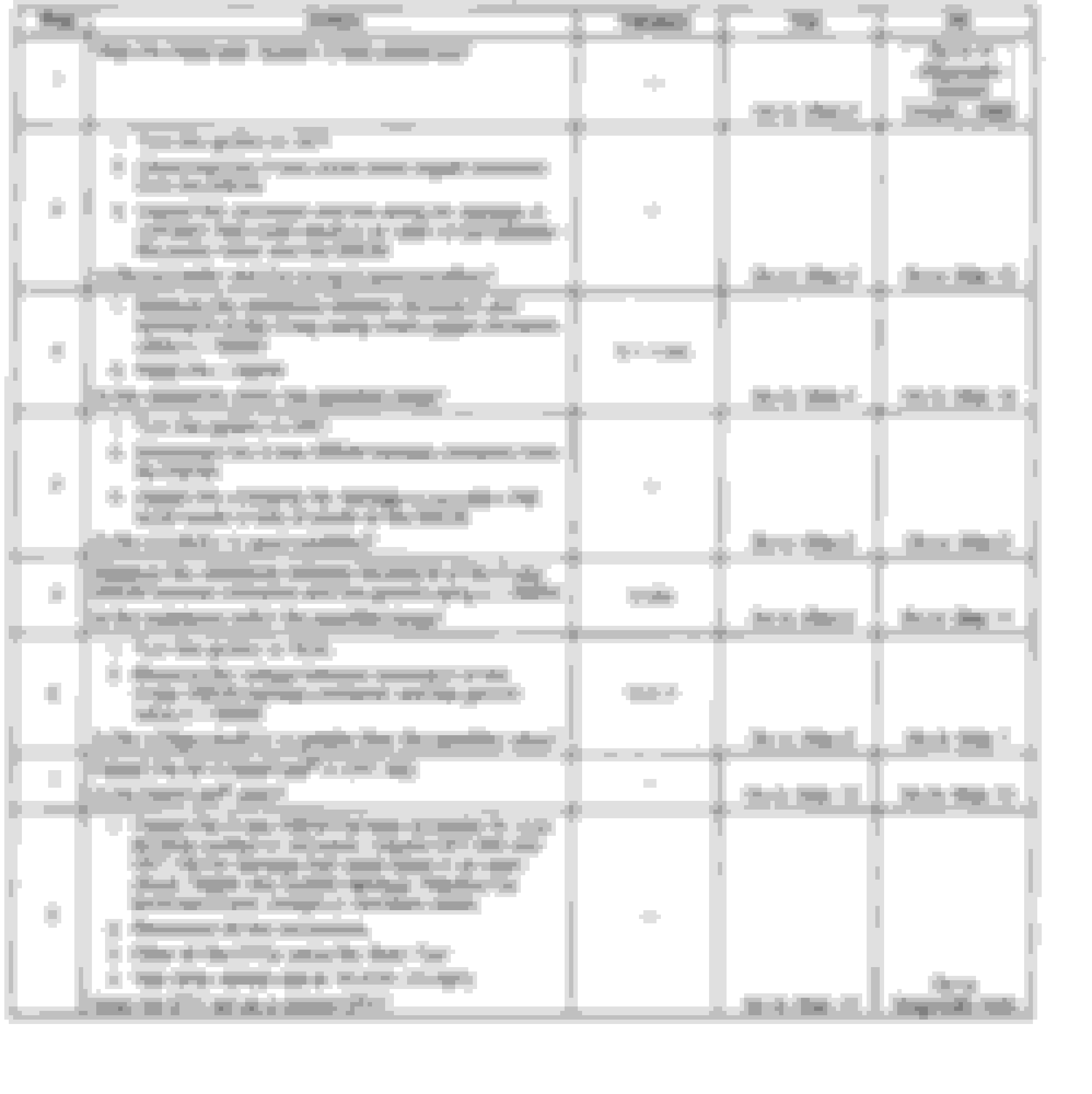
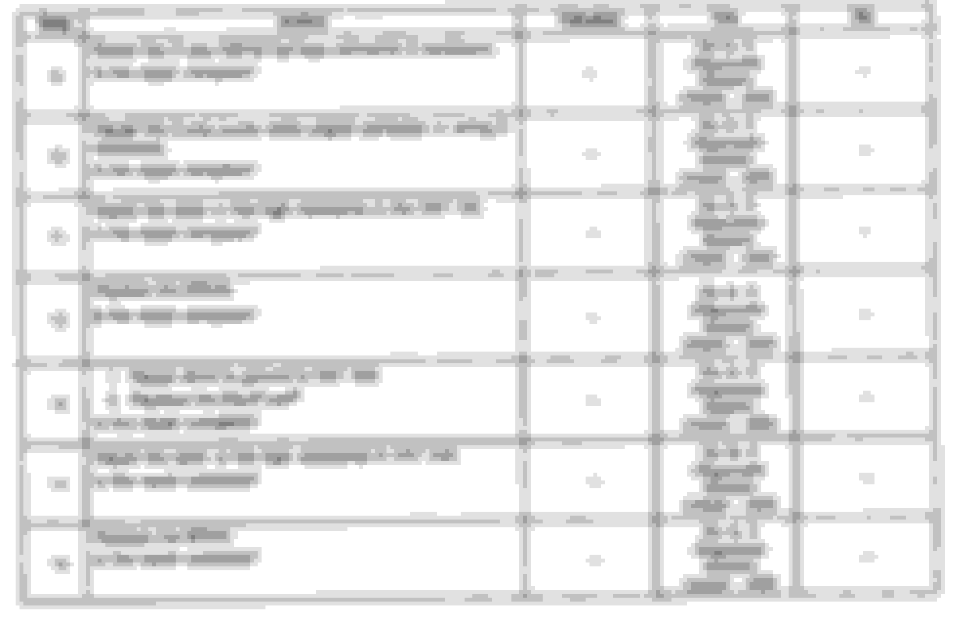
I got on all data and found the diagnostic charts for the code
And right at step 3 I found 1.4 ohms instead of 0.1-1 so I went to step 15; replace the BPMV. edit: measured wrong plug, but id still like to know what the BPMV is.
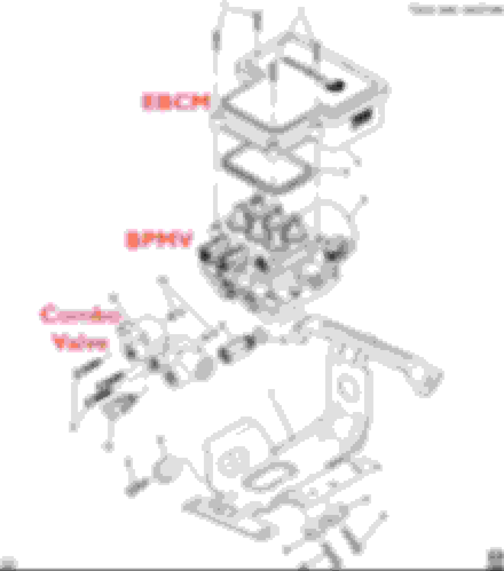
and this is where I need help. I had another ABS unit from another vehicle (same model) so I broke it down into its core 3 peices.. and I can't tell which is supposed to be the Brake Pressure Modulator Valve. My Google-fu lead me in confused circles as to what exactly this BPMV part is. So here's a Pic with what I think the parts are - can anyone clear this up for me? I
Last edited by BangMyHead; 04-12-2024 at 12:44 PM.
Unfortunately it appears the Circuit numbers are useless, as punching them in on alldata or Google gets sweet FA. Went through the diagnostics, all the voltages showed but I couldn't get any of the resistances measured 🤷♀️
I manually tested the ABS motor with direct power prior to installation to ensure it worked as the unit was used. However when we were bleeding it, I had to shoot compressed air up the brake line from the passenger rear in order to open the proportioning valve since I didnt have a tech 2 scanner.
I guess the ABS motor could've died between now and then, but I'm not convinced it's actually shorted and that whatever throws c0268 is just being triggered by the pump trying to run and then running against a stuck valve in the system..
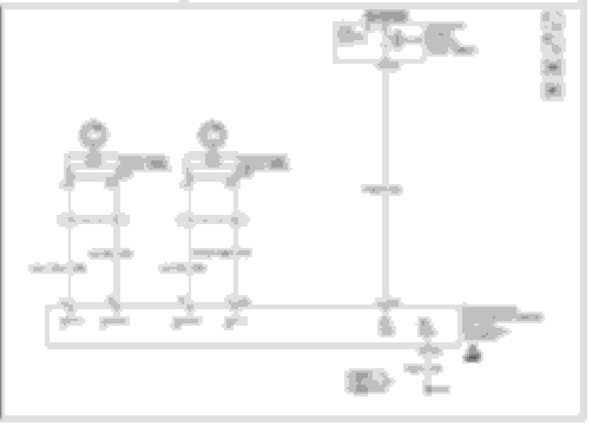
When you go into Alldata look at the OE Electrical Wiring Diagrams for circuit numbers, (not the colored diagrams). There you will see the circuit numbers. I'll take a look also.
When you go into the Alldata OE Diagrams you will see the original service manual wiring diagrams that look like the below. As you can see they will have the wire color, size and circuit number. Sometimes it's better to use the OE diagrams (not colored) sometime it's better to use the Alldata redrawn diagrams (colored)...sometimes you use both.
What happened (or what work did you do prior to the ABS light popping on?
If you disconnect the connector the connector at the EBCM and connect a test light between the harness connector side red & black wires (circuits 442 & 150) you should see a nice bright light. On a circuit like this that is coming directly from the fuse box and going directly to a ground I will even use higher amp draw lights (like stop light bulbs or headlights I've rigged up) to insure a nice bright light. If you get a nice bright light, short may be in EBCM pump motor. But don't go crazy spending money and changing parts until you have done full diagnosis of the circuit(s).
What you are looking at on Alldata is the original service manual that the dealerships used (with the exception of colored wired diagrams which weren’t part of the service manuals). When you go thru the diagnosis for codes they have listed they tended to rely heavily on resistance measurements.
On newer car’s service manuals diagnosis they are doing much better at testing with current going thru circuits, but back in ’99 they weren’t so much. Because of that you can have a circuit with a corroded wire/connector, etc that will ohm correctly, but once that circuit actually has current going thru it (via a test light for example), it will fail. This can cause incorrect calls and expensive parts needlessly replaced. So don’t get super hung up on resistance measurements as your first go to. In general, that is the last thing I use for checking circuits…though there are exceptions.
Keep all this in the back of your mind when you are following the service manual troubleshooting steps. Also, the service manual steps can take much longer to find a problem then other methods. That being said, for someone trying to find a problem without experience or help using other methods it’s a good place to start. With each step look at the reason for the step and think about what is the step addressing in the circuit/component.
Many components are Pulse Width Modulated (PWM) and are not intended to have straight 12 volts applied to them. Doing so can give you erroneous conclusions and in some cases damage a component or circuit. Some components on your truck are designed for 5 volts. When doing diagnosis read up on exactly how the component and circuit works from power to ground. The service manual and wiring diagrams will tell you with research. Stabbing a connector with 12 volts or using a test light incorrectly could end up with damaged components or frying a driver in a computer (as an example). Know how the entire circuit and component works, then start your diagnosis. It will go smoother and help keep you from going off in different directions.
Well, the light was on previously - so I pulled unit and attempted to remove the plastic lid for the control module to try that solder-reflowing technique I had seen in a few posts. Unfortunately I completely destroyed the unit in my attempt to do so. So I picked up another unit from a scrapyard and installed it. At the time of installation, I turned the engine on to confirm the ABS light was off, and it was... until the moment I put the vehicle back on the ground and put it in drive. I ignored it for some time as I was working on other issues and I figured it was just in need of more bleeding. But now the time has come!
Thank you for clearing up how to read the electrical diagrams! I'm way less confused now, I didn't realize the number alongside the wire identifier was the circuit number. I'll keep your advice about not relying on the resistances too much as I begin testing things here. I've got a pile of old stop light pigtails, so I'll pop a bulb in one and use that as needed.
Don't suppose you know of any other threads on the forum you could link as reference reading? Searching for abs related issues got me limited success, most threads seem to wrap up the moment somebody mentions module masters 😅.
1. Just to clarify, as I stated there are times when ohm measurements are the way to go. But in most cases when I am actually "measuring resistance" I am doing that by measuring voltage drop with current applied and using volt meter. This is just in general, not necessarily yet specific to your current issue.
2. When you make up stop light pigtails you want to measure and label their amp draw using a fully charged 12 volt battery (I use a spare lawn tractor battery). There are many videos on how to do this with your amp meter. You don't want to stab a pigtail setup into a circuit that can't carry the current (due to smaller wire gauge for example). The example I gave is because circuits 442 &150 can carry the current of a stop light bulb. Know your circuit. When in doubt and not completely sure only use the test light.
3. Did the ABS unit come off the same truck you have? There are several versions of different types of GM truck ABS units that look exactly the same on the outside, but internally are different. Not sure on S/T trucks. Best to go by the RPO code for your ABS system when pulling off another truck. RPO sticker is in the glove box and is kind of like the build sheet for your truck. I have a video saved I'll have to find that meticulously goes thru a code similar to what you have and also explains about different ABS units.
Here is the video I was referring to. If I remember right he is working on a C/K truck but all the fundamentals are the same as far as using the Service Manual step by step process. It is a long video, but I think would be good for you to watch. Admittedly there is a thing or two he states I don't necessarily agree with concerning work on the EBCM. But I'm personally comfortable working on circuit boards.
Well I found the culprit! After probing the ECBM plug I discovered that circuit 150 was broken. Lifted up the fuse box, and sure enough- I had forgotten to hook up ground 110 to the frame. Slapped that sucker back on there and the ABS light is now off! Went up and down the driveway without coming back on, so I'm thinking it'll be good.
As to the units looking similar but being different - I didn't even think of that at the time. How can I ensure I got the right one? The model number sticker on the top is long gone for both the orginal unit, and the one from the scrapyard. There's an additional model# on the body of the ABS motor itself - can that be used as a reference?
The blazer I pulled it from was a 4 door 2000. Next time I'm in town I'll pop back in the yard and take a pic of the RPO and see if it matches mine. In the event I did grab the wrong unit, what should I lookout for some in terms of some serious malfunction or erroneous operation?
Watch that video I posted. He really goes into detail on the ABS units as he's going thru testing. Very informative.
Things to watch for are the ABS light (always pull codes to make sure it isn't something else); when coming to a stop does the ABS kick on in the last few feet (when it shouldn't). Little concerned with you shooting compressed air up there. Hope you bled brakes after that. ABS system might need to bled. But you need capable scan tool to do that. But if all braking is normal, don't worry about it at all. You'll know if there is a problem.

 04-12-2024 | 12:19 PM