
Side mirror control switch wiring


Thread Starter
|
New Member
Joined: Nov 2008
Posts: 5

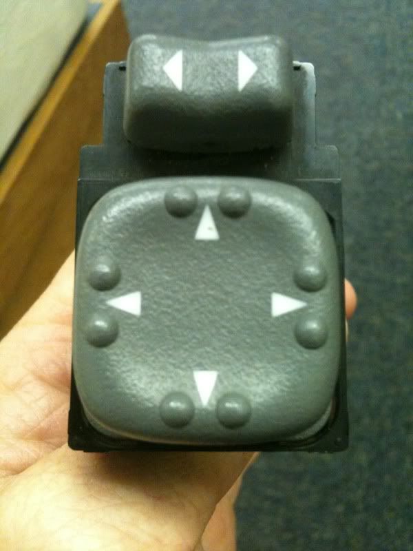
Does anyone have a wiring diagram for this mirror switch? I have been google-ing for over an hour but have not found anything useful. I believe it's from a 99 if that matters. It has 9 wires off the harness:
brown
black
green
yellow
yellow
white
orange
red w/ white
purple w/ white
I appreciate any help!
brown
black
green
yellow
yellow
white
orange
red w/ white
purple w/ white
I appreciate any help!


Starting Member
Joined: Oct 2009
Posts: 193

Get a digital multimeter that has a continuity setting. Put one probe in one pin on the back of the switches and put the other on a nearby pin, push all the buttons/switches until the multimeter shows continuity, if it doesnt show continuity for any of the buttons move one probe to a different pin and try again.
Keep doing that and eventually you will map out which pins are wired to each switch/button.
Keep doing that and eventually you will map out which pins are wired to each switch/button.
Thread Starter
|
New Member
Joined: Nov 2008
Posts: 5
Get a digital multimeter that has a continuity setting. Put one probe in one pin on the back of the switches and put the other on a nearby pin, push all the buttons/switches until the multimeter shows continuity, if it doesnt show continuity for any of the buttons move one probe to a different pin and try again.
Keep doing that and eventually you will map out which pins are wired to each switch/button.
Keep doing that and eventually you will map out which pins are wired to each switch/button.
I gave it another try and this is what I came up with just in case anyone else is looking for this info in the future.
Orange - battery
black - ground
yellow (either one), white, and green control driver mirror.
White + yellow controls side to side movement
green + yellow controls up and down movement
yellow (either one), red w/white, and purple w/ white controls passenger side mirror
red + yellow controls side to side movement
purple + yellow controls up and down movement
I think brown might be for illumination? I can't get it to do anything, so I'm not sure yet.
Thank you for encouraging me to try this again. It took some time and a 9 volt battery to figure it all out, but i think I'll get it from here.

Thread
Thread Starter
Forum
Replies
Last Post
Wexinlo
1st Generation S-series (1983-1994) Tech
5
Apr 6, 2011 11:35 PM
JohninMass
2nd Generation S-series (1995-2005) Tech
1
Nov 30, 2009 08:24 AM
George
2nd Generation S-series (1995-2005) Tech
3
Apr 18, 2008 11:15 AM