
Headlight relay upgrade, composite headlights

Thread Starter
|
BF Veteran
Joined: Sep 2011
Posts: 2,278
From: Texas

So, anybody else think the light output on our headlights sucks? I sure do. There are some threads on S10forum (HOW TO: Headlight Rewire - S-10 Forum and Headlight Rewire How-To 98+ - S-10 Forum )
about how to install relays to increase voltage to the headlights. These are very good, and helpful, but I figured it was time that we had one on our own site!
This applies to the composite headlights. That means you have two separate, removable bulbs in each headlight. Apparently the trucks didn't get this setup till '98, as the '98+ thread shows. However, this is the setup I have on my '95 Blazer, so maybe we got the good lights earlier? Who knows.
Anyway, it's pretty easy to install. Basically what you are doing is using the factory switch and wiring to energize the coil in the relay you install, which closes the contacts, providing battery voltage straight to the headlights. The factory wiring is quite small, and produces a drop in voltage:
With the factory wiring, my battery was showing 14.6V. The lows were receiving 13.4V, and the highs at 13.1V. According to a chart in a thread discussing the topic on here, I was getting about 400-500 fewer lumens than if the bulb was receiving battery voltage.
My final results, with battery at 14.57V, was 14.55V at the lows, and 14.54V at the highs.
So, here's what all I ended up needing:
Step one is to remove the grill

After that you'll need to remove the headlight. It's a good idea here to either take a picture, or notes to remember how everything goes once it's all apart. On mine, the upper bulb is the low beams, and the bottom are the highs. Also, on the factory wiring to the bulb, the black wire will always be the ground, and the colored wire is the power from the headlight switch on the dash.
Once the light is out, remove the connectors from the light. You will need a paper clip, or something similar to remove the ends from the connectors:

Here's the ends removed from the connector:

Now, with the ends out of the connector, CAREFULLY separate them from the wire. I used a small flat head screwdriver and bent back the larger crimp, shown on the tan wire above, and then bent them back and forth until the wire broke. You will need to solder these ends onto your new 10 gauge wire. I picked up this cheap iron and solder at Autozone for about ten bucks, and it got the job done pretty well.

I had never soldered before this project. It's not really difficult, you just need to be patient. You'll also notice there are no pictures of my soldering, either! That's because, while they were pretty strong and will hold, they were UGLY! LOL.
Once you get the new wire soldered on, bend the retaining clips back out, and insert them back into the connector. With the clip up on the connector, and the bulb end pointed at you, the ground will go on the left, and red (power) on the right.

Here's the new 10 gauge next to the tiny factory wiring

You will need to clean a spot to ground the black wire. I used the factory location on the radiator core support, after cleaning it up with some sandpaper.
Now it's time to get the relay ready. If they are anything like mine came, you will have two blue wires, and two reds. Remove all four of these, similar to how you removed the ends from the headlight connector. Pick one red, and one blue. Leave the center of the relay socket empty, and put the red in one relay, and the blue in the other. I was a dummy at this point, and forgot to take pictures, but there is a good explanation in one of the threads mentioned above.
The relay wiring is as follows:
Yellow - common positive from battery for both relays
Red - power to low beams
Blue - power to high beams
White - common ground for the switch
Black (2) - power from dash switch. (connected to the colored wire from factory wiring)
I mounted my relays close to the headlight. I'm a little concerned about water, though. I plan on going around the base, and where the relay mounts to the socket with silicone in the future to try and water proof it.

Connect the red wire from the low beams to either blue or red from the relay socket, red from the highs to blue or red from the socket (whichever one you didn't connect the lows to). Find a good place to ground the white wire from the socket. The colored power wire (factory wire) from the high beams will be connected to the black wire from the relay you connected the highs to, and the colored wire form the lows will go to the black from the low beam relay.
The black wire from the factory wiring isn't needed anymore. I guess you could attach the white wire to it, but I chose to ground mine next to the relay. I just stuffed to old black wires into the wire loom.
At this point you should be able to switch the headlight switch on the dash on, and read continuity from the yellow wire to the red wire on the low beams. (After hooking the battery back up) Flick on the highs, and you should have continuity form the yellow wire to the high beams. Go ahead and check all four relays are wired properly before running power to them from the battery!
I made a run with red wire from the battery positive to each yellow wire on the relay. If you have a side post battery, you will need to get a battery post extender. I couldn't get a ring terminal in there without one.
It's very important to put some kind of protection between the battery and relay, too, such as a fuse, or 12v circuit breaker. Since the low beams draw 55w, and highs 65w, that's only 4.5 and 5.4 amps, respectively. Even with the quad-beam mod and both on, it's 10 amps at the most. I plan on ordering a 20 amp breaker for each light on mine.
Once everything is wired up and working, cover all the exposed wires in split loom! I ended up needing two boxes of 10' 1/2" loom. Put your grill back on, adjust headlights as necessary, and enjoy your new lights!
If I missed something, feel free to ask!
about how to install relays to increase voltage to the headlights. These are very good, and helpful, but I figured it was time that we had one on our own site!
This applies to the composite headlights. That means you have two separate, removable bulbs in each headlight. Apparently the trucks didn't get this setup till '98, as the '98+ thread shows. However, this is the setup I have on my '95 Blazer, so maybe we got the good lights earlier? Who knows.
Anyway, it's pretty easy to install. Basically what you are doing is using the factory switch and wiring to energize the coil in the relay you install, which closes the contacts, providing battery voltage straight to the headlights. The factory wiring is quite small, and produces a drop in voltage:
With the factory wiring, my battery was showing 14.6V. The lows were receiving 13.4V, and the highs at 13.1V. According to a chart in a thread discussing the topic on here, I was getting about 400-500 fewer lumens than if the bulb was receiving battery voltage.
My final results, with battery at 14.57V, was 14.55V at the lows, and 14.54V at the highs.
So, here's what all I ended up needing:
- a digital multi-meter
- electrical tape
- 10 gauge wire. I happened to have enough black and red wire to make all the positive red, and the grounds black, but any color will work.
- crimpers, cutters, and a way to strip the wire.
- soldering iron/solder
- butt splices and ring terminals
- zip ties
- split loom. I used 1/2", 3/8" might have worked, though.
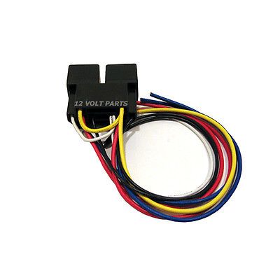
- and, of course, relays. I got mine on ebay. You will need four SPDT 12v relays. They might be called "Bosch style". Mine came mounted on a double relay socket, as well. It's possible to just put female connectors on your wire ends to attach to the relay, but I preferred sockets.

Step one is to remove the grill

After that you'll need to remove the headlight. It's a good idea here to either take a picture, or notes to remember how everything goes once it's all apart. On mine, the upper bulb is the low beams, and the bottom are the highs. Also, on the factory wiring to the bulb, the black wire will always be the ground, and the colored wire is the power from the headlight switch on the dash.
Once the light is out, remove the connectors from the light. You will need a paper clip, or something similar to remove the ends from the connectors:

Here's the ends removed from the connector:

Now, with the ends out of the connector, CAREFULLY separate them from the wire. I used a small flat head screwdriver and bent back the larger crimp, shown on the tan wire above, and then bent them back and forth until the wire broke. You will need to solder these ends onto your new 10 gauge wire. I picked up this cheap iron and solder at Autozone for about ten bucks, and it got the job done pretty well.

I had never soldered before this project. It's not really difficult, you just need to be patient. You'll also notice there are no pictures of my soldering, either! That's because, while they were pretty strong and will hold, they were UGLY! LOL.
Once you get the new wire soldered on, bend the retaining clips back out, and insert them back into the connector. With the clip up on the connector, and the bulb end pointed at you, the ground will go on the left, and red (power) on the right.

Here's the new 10 gauge next to the tiny factory wiring

You will need to clean a spot to ground the black wire. I used the factory location on the radiator core support, after cleaning it up with some sandpaper.
Now it's time to get the relay ready. If they are anything like mine came, you will have two blue wires, and two reds. Remove all four of these, similar to how you removed the ends from the headlight connector. Pick one red, and one blue. Leave the center of the relay socket empty, and put the red in one relay, and the blue in the other. I was a dummy at this point, and forgot to take pictures, but there is a good explanation in one of the threads mentioned above.
The relay wiring is as follows:
Yellow - common positive from battery for both relays
Red - power to low beams
Blue - power to high beams
White - common ground for the switch
Black (2) - power from dash switch. (connected to the colored wire from factory wiring)
I mounted my relays close to the headlight. I'm a little concerned about water, though. I plan on going around the base, and where the relay mounts to the socket with silicone in the future to try and water proof it.

Connect the red wire from the low beams to either blue or red from the relay socket, red from the highs to blue or red from the socket (whichever one you didn't connect the lows to). Find a good place to ground the white wire from the socket. The colored power wire (factory wire) from the high beams will be connected to the black wire from the relay you connected the highs to, and the colored wire form the lows will go to the black from the low beam relay.
The black wire from the factory wiring isn't needed anymore. I guess you could attach the white wire to it, but I chose to ground mine next to the relay. I just stuffed to old black wires into the wire loom.
At this point you should be able to switch the headlight switch on the dash on, and read continuity from the yellow wire to the red wire on the low beams. (After hooking the battery back up) Flick on the highs, and you should have continuity form the yellow wire to the high beams. Go ahead and check all four relays are wired properly before running power to them from the battery!
I made a run with red wire from the battery positive to each yellow wire on the relay. If you have a side post battery, you will need to get a battery post extender. I couldn't get a ring terminal in there without one.
It's very important to put some kind of protection between the battery and relay, too, such as a fuse, or 12v circuit breaker. Since the low beams draw 55w, and highs 65w, that's only 4.5 and 5.4 amps, respectively. Even with the quad-beam mod and both on, it's 10 amps at the most. I plan on ordering a 20 amp breaker for each light on mine.
Once everything is wired up and working, cover all the exposed wires in split loom! I ended up needing two boxes of 10' 1/2" loom. Put your grill back on, adjust headlights as necessary, and enjoy your new lights!
If I missed something, feel free to ask!
Last edited by cleburne red; Jan 20, 2014 at 05:28 PM.
Excellent write up indeed.
One question though, can you really tell a difference? I find 400 - 500 less lumens to be quite unbelievable, as 55W halogens really only put out about 1300 to begin with.
One question though, can you really tell a difference? I find 400 - 500 less lumens to be quite unbelievable, as 55W halogens really only put out about 1300 to begin with.
Thread Starter
|
BF Veteran
Joined: Sep 2011
Posts: 2,278
From: Texas
I got the lumens figure from this thread: https://blazerforum.com/forum/2nd-ge...dlights-75913/
I didn't fact check that chart, myself, though.
My headlights do appear brighter, but how much of that is the extra volt or two, versus actually having them aimed properly, I'm not sure. They were pretty far off before, and now they are actually aimed at the road.
Either way, I still enjoyed the project, and since I already had wire, I was only out the cost of the relays and sockets, about $20.

Thread
Thread Starter
Forum
Replies
Last Post
mamawolf70
2nd Generation S-series (1995-2005) Tech
1
Apr 1, 2015 12:25 PM
donnieb83
2nd Generation S-series (1995-2005) Tech
1
Aug 2, 2008 08:05 AM
bestes
1st Generation S-series (1983-1994) Tech
2
May 31, 2008 03:16 PM
S10Blazer
Paint, Body, & Interior
1
Nov 3, 2006 08:41 AM