
"HOW TO: Wire a Flex-a-Lite VSC Electric Fan Controller"


Thread Starter
|
Starting Member
Joined: Aug 2010
Posts: 196
From: St Louis

I am going to walk you thru wiring for the install of the Flex-a-Lite Variable Speed Controller into you S-series truck. Very simple install. Install was on a 2003 Blazer ZR2
Here is a link to the VSC instructions:
http://www.flex-a-lite.com/auto/31165-99943.pdf
I did not take pictures as I was installing it. But I can show you the wires to tap.
I mounted my VSC on the lower engine side of the air box. Out of the way some what stealth install.

DISCONNECT BATTERY
Terminals
#1 Black Pre-wired
Battery Negative (-)
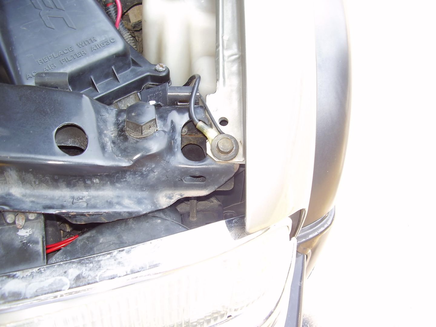
Install ring terminal and ground at bolt for fender to core support. (I tested and found less than .25 ohm between here and battery) 13mm bolt
#2 Purple Pre-wired
Negative to fan
Hook this to the negative wire for the fan
#3 Yellow Pre-wired
Positive to fan
Hook this to the positive wire for the fan
#4 Red Pre-wired
Battery Positive (+)
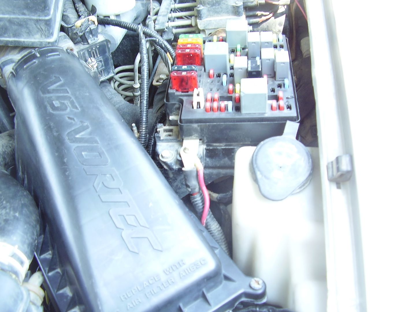
Install ring terminal. Install ring terminal on Battery positive stud on side of fuse box.

#5 Negative override OFF
#6 Negative override ON
These two connections are optional. Follow diagram on supplied instructions to hook up.
#7 AC Negative Signal
This terminal is not used for a S-series install
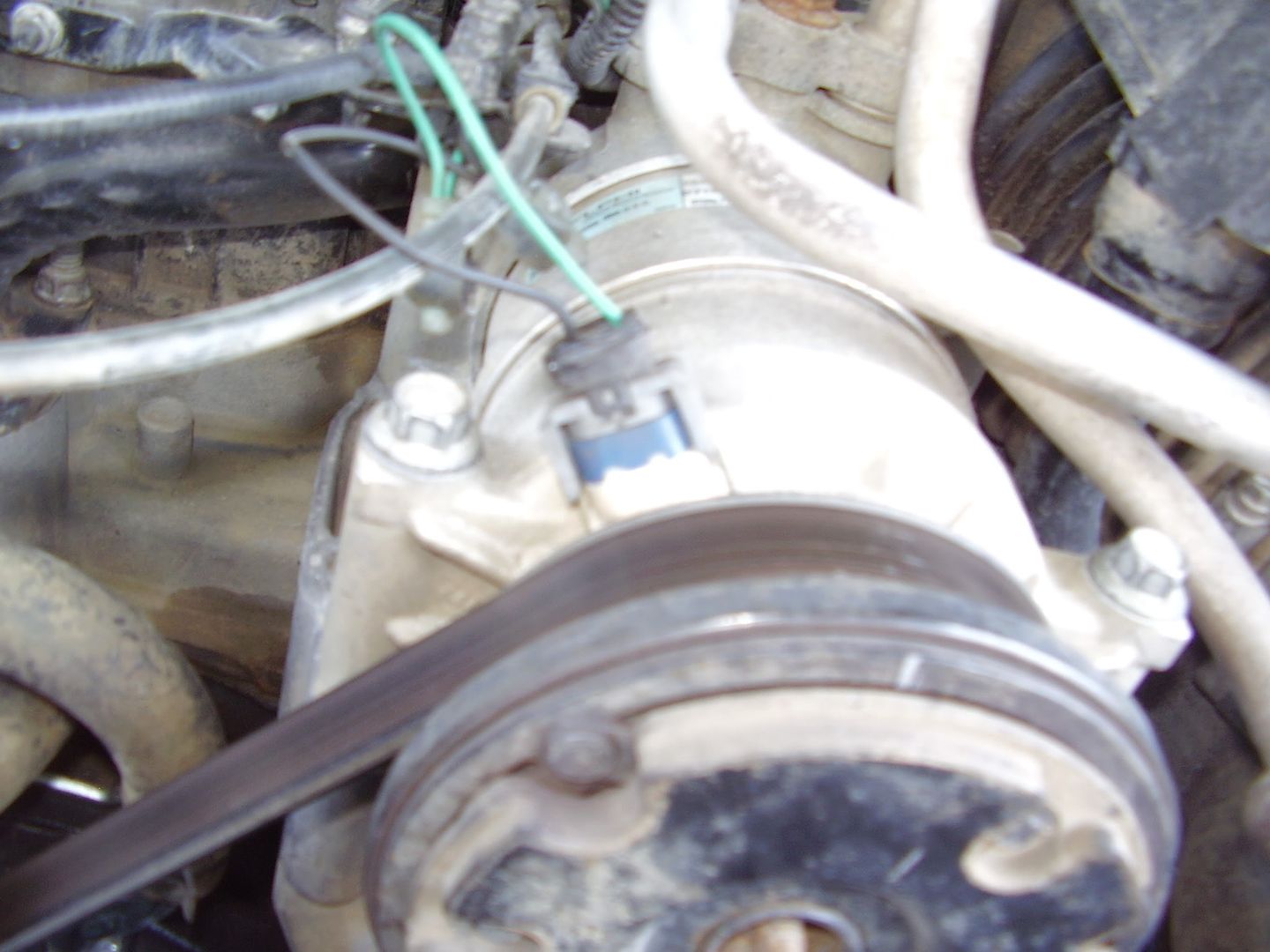
#8 AC Positive Signal
Using a side by side tap connector, tap the green wire for the AC Compressor Clutch. It is located on the top front of the compressor. This wire will cycle with the compressor.
I tapped into a different wire so you won't see a connection here (blue wire on connector on back side of compressor). The blue wire will have the fans on when ever you request the ac, whether the compressor is running or not. It's your choice on which one you would like to tap.

#9 Ignition Positive Signal
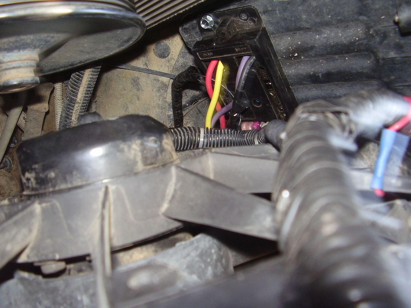
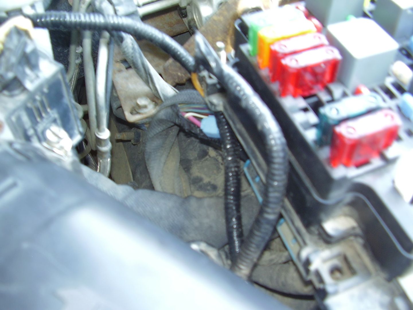
For this connection it will be easier to unbolt fuse box. 3 10mm bolts. Once you have the box flipped over, remove the bottom cover. Locate the Gray connector. Now on this connector locate slot A9. That slot contains a PINK wire. The wire is noticeably thicker than the other wires surrounding it. This wire is coming from the ignition switch and is supplied power when the key is in the run position. Cut the harness loom back 5-6". Using a side by side tap connector, tap the pink wire. Reinstall the bottom cover for the fuse box and reinstall the box itself.

Here you can see the pink wire in the loom outside the fuse box with a blue tap connector on it.

#10 and #11 are your temperature probe terminals.
I followed HenryJ's LS1 fan install:
http://www.s-10crewcab.net/HenryJ/fans/fans.html
Here is a link to the VSC instructions:
http://www.flex-a-lite.com/auto/31165-99943.pdf
I did not take pictures as I was installing it. But I can show you the wires to tap.
I mounted my VSC on the lower engine side of the air box. Out of the way some what stealth install.
DISCONNECT BATTERY
Terminals
#1 Black Pre-wired
Battery Negative (-)
Install ring terminal and ground at bolt for fender to core support. (I tested and found less than .25 ohm between here and battery) 13mm bolt
#2 Purple Pre-wired
Negative to fan
Hook this to the negative wire for the fan
#3 Yellow Pre-wired
Positive to fan
Hook this to the positive wire for the fan
#4 Red Pre-wired
Battery Positive (+)
Install ring terminal. Install ring terminal on Battery positive stud on side of fuse box.
#5 Negative override OFF
#6 Negative override ON
These two connections are optional. Follow diagram on supplied instructions to hook up.
#7 AC Negative Signal
This terminal is not used for a S-series install
#8 AC Positive Signal
Using a side by side tap connector, tap the green wire for the AC Compressor Clutch. It is located on the top front of the compressor. This wire will cycle with the compressor.
I tapped into a different wire so you won't see a connection here (blue wire on connector on back side of compressor). The blue wire will have the fans on when ever you request the ac, whether the compressor is running or not. It's your choice on which one you would like to tap.
#9 Ignition Positive Signal
For this connection it will be easier to unbolt fuse box. 3 10mm bolts. Once you have the box flipped over, remove the bottom cover. Locate the Gray connector. Now on this connector locate slot A9. That slot contains a PINK wire. The wire is noticeably thicker than the other wires surrounding it. This wire is coming from the ignition switch and is supplied power when the key is in the run position. Cut the harness loom back 5-6". Using a side by side tap connector, tap the pink wire. Reinstall the bottom cover for the fuse box and reinstall the box itself.

Here you can see the pink wire in the loom outside the fuse box with a blue tap connector on it.
#10 and #11 are your temperature probe terminals.
I followed HenryJ's LS1 fan install:
http://www.s-10crewcab.net/HenryJ/fans/fans.html
Last edited by stlwaco; Jul 28, 2011 at 03:18 PM.

Nice write up. I linked to the automatic thumbnails because those pictures were quite large.
Do you have any scans or links to the product literature for the controller you used? What fans did you install? Probably are questions that others will ask.
Do you have any scans or links to the product literature for the controller you used? What fans did you install? Probably are questions that others will ask.


Thread
Thread Starter
Forum
Replies
Last Post
iamchevyman5
Lighting & Electrical
8
Aug 13, 2015 02:32 PM
davedidit
2nd Generation S-series (1995-2005) Tech
17
Mar 6, 2011 04:48 AM
DetailersDomain
Detailing
0
Feb 19, 2011 07:30 PM
ExplicitYourSelf
Audio/Video Electronics
3
Jan 31, 2011 10:14 AM