When you click on links to various merchants on this site and make a purchase, this can result in this site earning a commission. Affiliate programs and affiliations include, but are not limited to, the eBay Partner Network.
99 chev blazer. No spark from ignition coil to distributor. I've bypassed the wire to my ignition control module with 12v and was able to get spark @ ignition coil. I'm reading codes p0336 and p0339 I've replaced my crankshaft ps with the same issue. Any ideas?
https://blazerforum.com/forum/tech-a...anks-ok-45942/
Found this gem and after following steps i found I have to:
Repair short to ground in coil driver circuit between ignition coil and ignition control module. After repairs, go to step 37 .
Could someone please give me direction on how to go about doing that? I feel so dumb right now. Please and thank you!
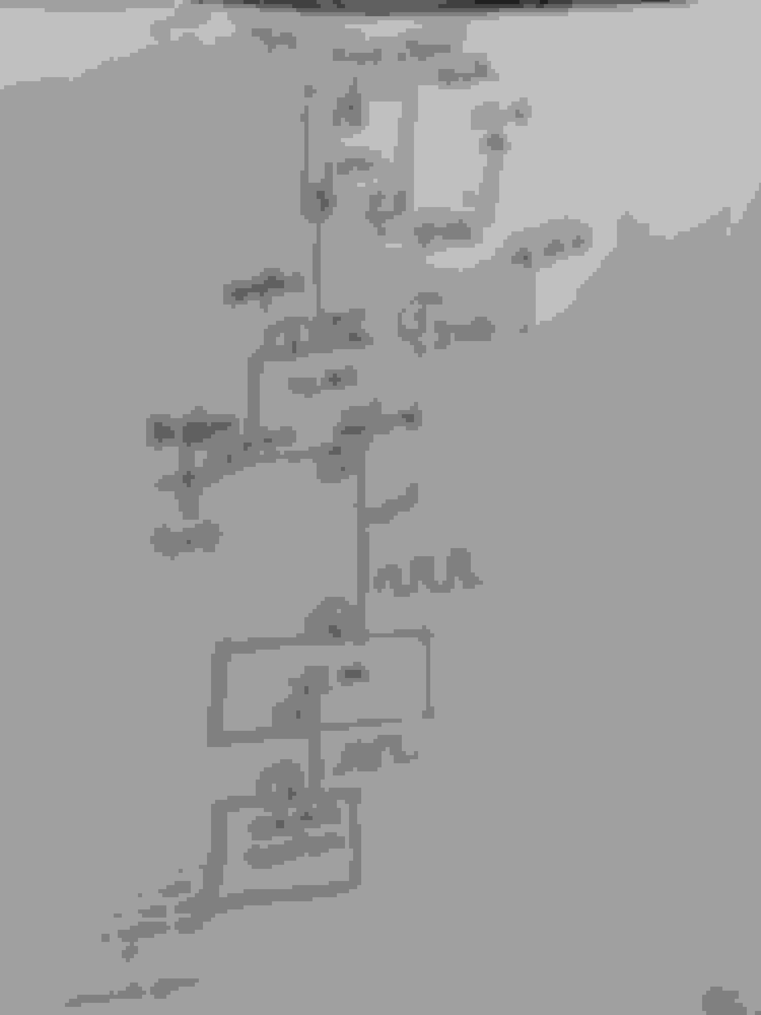
Lets get you straightened out. It looks like you got here from steps: 6/28/37. Lets make sure that this is really your problem and lets get up to speed on how the system works so your an ignition wiring pro. In my attached drawing:
The crank sensor sends a low power timing signal to the VCM to indicate crank position from J to I
The VCM sends the crank timing to the ICM from H to G on the white wire
The ICM takes that low power crank timing signal from the VCM and produces a ground side switching sequence that can handle the coil power and opens/closes to ground the coil primary winding from D to B on the wht/blk wire
This constant open/ground sequence on the wht/blk wire cause the coil primary winding to keep charging to 12v and then collapsing which induces the 25,000v spark in the coil secondary windings which goes to the distr
Failing step 6 suggests that the wht/blk wire between D and B is not a simple direct connection but somewhere that wire or either connector is shorted to ground. We can verify that by disconnecting that wht/blk wire from the coil at B and the ICM at D and then measuring the resistance from that open and unattached wire to battery ground. What is that resistance value? If a short to ground is confirmed then you either locate the wiring fault and correct it or run a new wire.
George
Thanks for the quick reply i can confirm it is reading ohm. I dont know the exact number because the multi meter im using isnt digital and i dont know exactly how to read it but i can confirm it spikes if i move the wire around.
Where is that blk/white wire running from. I don't want to rip that harness apart I'd rather just run a new line. Could you please help me? Do I just need to rewire from b to d?
The information that you provided does not confirm the failure so I cannot confirm that this will fix your problem. It would be a shame to hack into your wiring harness for the ignition function and make it less reliable when this may not be your problem. I have been doing this a long time and I am trying to keep you out of trouble. That said, its your truck and your call. I am here to help you.
Are you asking for help to locate this wire so you can replace it, asking for step by step instructions on how to cut it out, solder and shrink wrap in the replacement or both?
I guess, since that doesn't confirm a failure I would like to know what process you would go through now. I can confirm test light hooked up to positive terminal on battery and touching the black white wire produces a steady light. Doesn't that mean go to step 28 and replace the black white wire? I appreciate your fast reply. This is my daily driver I am hoping to get it running to take me to work tomorrow.
My shop manual is for a 2002 Blazer so double check all the wire colors and connector positions to make sure we are both dealing with the same exact wiring and connectors.
Disconnect the connector at the coil (6) and the ICM (5) so that the white/black ignition control wire is not connected to anything
Put your meter in the resistance measuring mode on the lowest scale. If you don't understand this, send me a picture of the meter so I can guide you.
Connect one lead of the meter to battery ground and the other lead of the meter to the wht/blk wire. You have to be certain that the connections are solid or else you may get misleading results. I am not at the truck today so I can't see if these connectors are molded and closed off on the back by the wires or open. If open back probe to touch the wire with a T pin or sewing needle or paper clip if it fits. If you have to go into the business end, do not force the probe or you will distort the connector contact and ruin the connector
Record the reading. If you don't understand the meter, take a picture and post it. Move the harness around making sure the meter is solidly connected and watch the meter
Report back. It doesn't matter what kind of meter it is as long as its working ok. I used an analog meter for 20 years and still own one. They are actually better for certain things. You can test your by putting one lead on the battery negative terminal and you should have a reading of infinite ohms of resistance. Now place the other lead on a good clean spot on the engine or frame and the reading should go close to zero, usually less than one ohm.
George
Last edited by GeorgeLG; Jun 11, 2023 at 11:07 AM.
I can confirm the wiring is the same on my 99. That setting is on the 1X ohm one terminal on the bat neg the other on the wht/blk D cable with with both terminals unplugged from the coil and ICM