2nd Generation S-series (1995-2005) Tech Discuss 2nd generation S-series (1995-2005) general tech topics here.

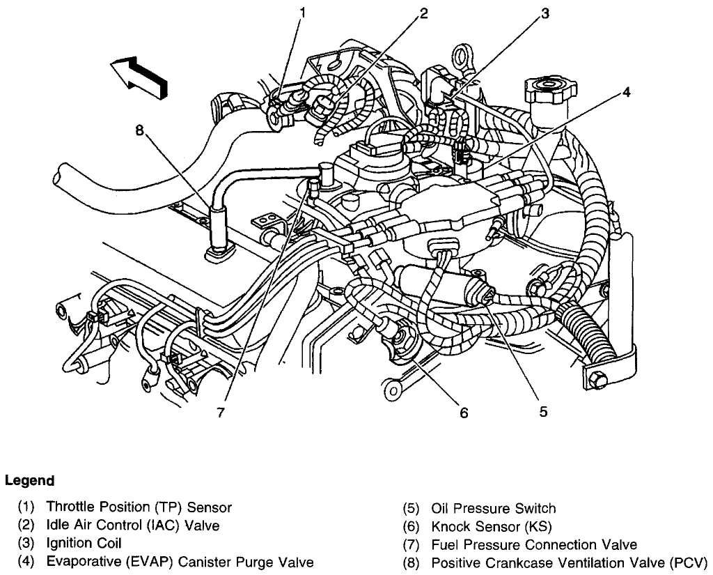
Anyone got a pic of the PCV system routing?

Thread Tools
 
Search this Thread
 
  #1  
Old 04-23-2010, 10:26 AM
midnightbluS10's Avatar
Junior Member
Thread Starter
Join Date: Mar 2007
Location: Shreveport, LA
Posts: 401
midnightbluS10 can only hope to improve
Default Anyone got a pic of the PCV system routing?

Mine has a leak at the elbow. Trying to make sure I have everything routed correctly. I bought a new elbow at the dealership, but it seems to be the wrong one. It's way to big for the connection I'm trying to make. I need a pic of the hose running from the PCV valve all the way to the "solenoid" on the int manifold. Thanks.
 
  #2  
Old 04-23-2010, 10:54 AM
swartlkk's Avatar
Administrator
Join Date: May 2005
Location: Waterloo, NY
Posts: 41,137
swartlkk has a reputation beyond reputeswartlkk has a reputation beyond reputeswartlkk has a reputation beyond reputeswartlkk has a reputation beyond reputeswartlkk has a reputation beyond reputeswartlkk has a reputation beyond reputeswartlkk has a reputation beyond reputeswartlkk has a reputation beyond reputeswartlkk has a reputation beyond reputeswartlkk has a reputation beyond reputeswartlkk has a reputation beyond repute
Default

Here ya go:
 
  #3  
Old 04-23-2010, 02:27 PM
midnightbluS10's Avatar
Junior Member
Thread Starter
Join Date: Mar 2007
Location: Shreveport, LA
Posts: 401
midnightbluS10 can only hope to improve
Default

Originally Posted by swartlkk
Here ya go:

Thanks. I actually found that pic while searching. I'm trying to figure out how this "T" fitting fits into the equation with the vac lines. The way I've got it now, a 4" long vac line comes off of the solenoid and then there's the "T". The line with the check valve is connected to one leg and the line that goes to the vac canister in the fender is connected to the other leg. Is that right?
 
  #4  
Old 04-23-2010, 03:37 PM
swartlkk's Avatar
Administrator
Join Date: May 2005
Location: Waterloo, NY
Posts: 41,137
swartlkk has a reputation beyond reputeswartlkk has a reputation beyond reputeswartlkk has a reputation beyond reputeswartlkk has a reputation beyond reputeswartlkk has a reputation beyond reputeswartlkk has a reputation beyond reputeswartlkk has a reputation beyond reputeswartlkk has a reputation beyond reputeswartlkk has a reputation beyond reputeswartlkk has a reputation beyond reputeswartlkk has a reputation beyond repute
Default

Shouldn't be a solenoid involved. It should connect right into the intake plenum. There may be a plastic clip that it goes into, but not a solenoid. From there, it goes to the check valve, then a 'T' and another 'T' (if 4wd). The three lines off of the 'T's should go to the vacuum reservoir located inside the driver side fender, the HVAC system (aka into the firewall), and, if 4wd, down to the transfer case switch (or up to the electronic solenoid on the firewall if equiped with the 4-button NV236 transfer case).
 
  #5  
Old 04-24-2010, 11:17 AM
midnightbluS10's Avatar
Junior Member
Thread Starter
Join Date: Mar 2007
Location: Shreveport, LA
Posts: 401
midnightbluS10 can only hope to improve
Default

Ok, so it's not a solenoid. I just assumed it was. It sounds like I've got everything hooked up right. Thanks, again!
 
Related Topics
Thread
Thread Starter
Forum
Replies
Last Post
rich27
Lighting & Electrical
0
10-23-2014 01:16 AM
landob123
2nd Generation S-series (1995-2005) Tech
1
06-10-2014 08:11 PM
rsheltro
2nd Generation S-series (1995-2005) Tech
6
12-26-2008 09:11 PM
Ken_C
Audio/Video Electronics
4
10-16-2008 01:26 PM
va454ss
2nd Generation S-series (1995-2005) Tech
2
02-17-2008 08:45 AM


Quick Reply: Anyone got a pic of the PCV system routing?


All times are GMT -5. The time now is 02:51 PM.