Anatomy of the Ignition Switch
#31
 02-05-2023, 11:14 AM


Bought a 04 LS 2dr, 2wd blazer from my boss that wasn't running,... Went from no spark, good fuel to good spark no fuel, I now have no power to the fuel pump unless I jumper the 30 to 87 terminals in the underhood fusebox..I know it will be the ignition switch but does any one have a wiring schematic for the ignition switch to the underhood fusebox? Please?

#33
12-29-2023, 02:45 PM

To start, the diagrams below are specific to the 2000 model year, but should apply to the 98+ trucks. The failure mode is the same for the earlier trucks though.
Quite a while ago, another member had sent me a working, but used ignition switch. I had said at the time that I would dissect it and show everyone how it works or at the very least, what goes wrong. During the disassembly process, I took out one too many screws ( ) and the thing popped apart like an antique clock, springs flying all over the place.
  Needless to say, I lost some of them and others I just could not return to their proper positions. So I am not able to discern which position is which (ACC, LOCK, OFF, RUN, START), but I will go through how it works and what goes wrong stages of the discussion.
So... Onto the article:
Anatomy of an ignition switch...
This is such a common problem on many s-series trucks. If weird things start happening with your truck and nothing seems to make any sense the culprit could possibly be the ignition switch.
Ignition switch diagrams:
C211 Connector Views:
So how does it all work?
The ignition switch uses a gear that has a few different ramps on either side of it. When you turn the key, the ignition cylinder drives the gear into its different positions. As the ramps pass under each of the small little followers, it acts as a sort of cam that pushes on each of the contact arms. The pictures below do not include any of the gear detents and the main spring on the gear has also been removed (the spring is what pushes the key back after you have started the vehicle).
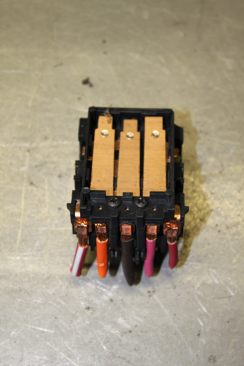
As you can see, there are five main contacts in the switch. These contacts control everything in the truck. For instance, the large brown wire in the middle/top portion of the switch is the accessory power wire which feeds into the RAP (retained accessory power) relay then off to all the accessory items (radio, windows, etc). The large orange wire is the IGN 3 wire which powers the ABS, HVAC, 4WD, and cruise systems. The large pink wire is the IGN 1 wire that powers the ECM, ENG 1 fuse, O2 sensors, B/U lamps, DRLs, A/C relay, etc.
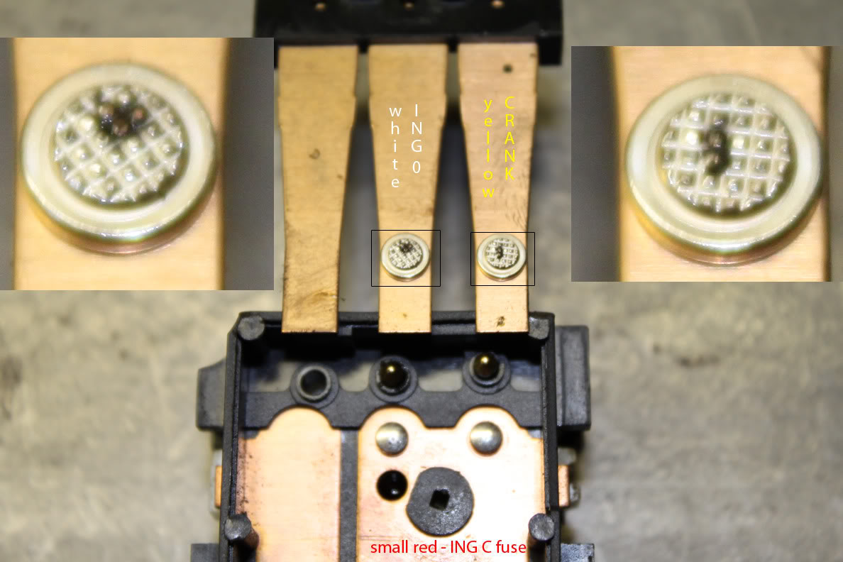
On the other side, you have the small white wire which feeds the IGN 0 circuit (cluster) and the small yellow wire which feeds into the starter circuit. These two items get power from the small red wire (IGN C fuse) when their respective contacts connect.
Here is a run down of what circuits have power for a given key position (ACC, LOCK, OFF, RUN, & START):
Since some of the circuits can have a fairly high current load on them when you start your truck, the arc that happens when the contacts close can be pretty intense. Over time, the contacts will erode/corrode and will loose their conductivity to each other, usually in the form of a higher resistance. This higher resistance also causes heat which further exacerbates the problem.
So what does it all look like?
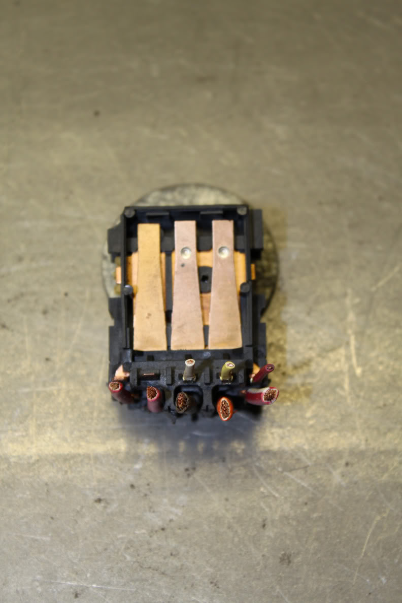
The first two pictures below are of the two contact sides of the ignition switch. All of the protective covers have been removed and the wiring has been cut short to allow for better photographs.
The next two photos show the contact arms removed from the switch housing, revealing the contacts themselves and displaying the charring that will eventually cause the switch to fail. I have zoomed in on the contact surfaces showing the most charring on each side.
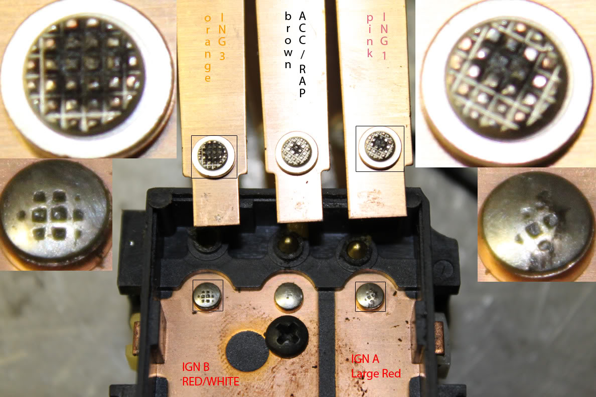
As you can see, the IGN 3 contacts are showing the most damage with the IGN 1 contacts starting to show the affects of age as well.
The IGN 3 contacts are the most heavily loaded of all of the contacts in the system and it also is the contact which is opened and closed the most during the life of the truck. Lets look closer at what this contact goes through on a normal start sequence. In a typical start cycle, the key is turned from LOCK, through OFF and RUN, then to START, and finally back to RUN once the vehicle is started. As the key is turned from LOCK to RUN, the IGN 3 contacts close. When the key is then turned to START, the contacts open back up. Once returned to RUN, the contacts close again. This is why it is vitally important to hold the key in the START position until you are sure that the engine is running. The more times you go to the START position, the more life you take away from these contacts.
So what happens when the contacts go bad?
For the 98+ trucks, the most common issue is the "security" light on the dash illuminating. But the problem can also manifest itself as an inoperative fuel pump, unresponsive cluster, ABS and/or SIR lights being illuminated on the cluster, as well as a no start condition (either related to the inoperative fuel pump or a failure of the starter to turn over). The ignition switch can also cause PASSLOCK issues.
All of the pictures and diagrams above are pertinent to the 98+ trucks. The ignition switch found in the 96-97 trucks is quite similar, but the 1st gens and fullsize trucks are very different.
How do I diagnose a bad contact:
On approach to diagnosing ignition switch issues starts by disconnecting the ignition switch harness below the steering column. This requires you to pull off the lower dash knee bolster and reinforcement brace. Once there, you should see the main ignition switch harness connector which is bolted together. Loosen the captive bolt & pull the harness apart.
Testing will be done using a multimeter set to test circuit resistance. Check that your leads read zero resistance when touched to each other before moving on. If they do not, you have a problem with your multimeter, leads, or connections themselves and should find another to use for further testing.
Using the information provided below the connector pinouts concerning the circuit inputs, outputs, and pin numbers, probe each set of contacts & test the resistance in all of the key positions noted. A good contact should have a near zero ohm resistance. If the resistance varies or is over a few ohms, then the contacts are likely compromised. A resistance of even a few ohms can cause the contacts to heat up worsening the condition to the point of excessive voltage drop or all out circuit interruption.
Alternatively, testing on suspect contacts can be performed by back probing the contacts in the main ignition harness with the harness still connected and monitoring the voltage present on each circuit. The voltage should remain the same as the main system voltage. If it wavers or drops out as load is applied through various uses on that circuit (radio, windows, seats, lights, etc.), that contact is most likely compromised.
Voltage drop is another method of testing a live circuit whereby you test for the change in voltage from one side of a circuit to the other. In the case of the ignition switch, you would want to test from the input side of a contact to the output side of that contact and observe the voltage drop. For instance, if you were to back-probe cavity B1 (red wire) and cavity C5 (pink wire) in the ignition switch wiring harness with your multimeter probes, and observe the voltage drop, you could see if there is something out of the ordinary with the IGN1 contacts inside the ignition switch which is responsible for powering a number of critical engine control fuses.
^^^^Each mention of voltage drop in the paragraph above has a link to a separate article discussing the testing of voltage drop & how it can be used.^^^^
*EDIT 28SEP19*
Given the number of weird issues with the cluster that have popped up on the forums recently, I have been revisiting this thread quite a bit and have come up with some new methods for diagnosing these circuits. It occurred to me that there were fuses further down these circuits were we could test for voltage drop so here are a few, easier places to check for voltage drop.
Check the following fuses for voltage through the ignition switch:
One thing worth noting when testing at the fuses is that the voltage drop may be slightly higher here due to the increased resistance from the additional contact points in the system which may have aged over time (corrosion/tarnish on the fuses and other terminals along the circuit) which might not directly relate to a poor circuit.
Here is an Amazon link to a set of back-probe terminals that I have found extremely helpful in testing connected sealed & non-sealed connections without damaging the seals nor the terminals inside: Lisle 65150 Flexible Back Probes - Amazon.com
/end article
I am sure that there are more symptoms as well as information that I have left out. So I would be very pleased for everyone to take a look at this article and ask questions, give their experiences, and let us all know what needs to be added, removed, or corrected.
Thanks and I hope this helps!
Quite a while ago, another member had sent me a working, but used ignition switch. I had said at the time that I would dissect it and show everyone how it works or at the very least, what goes wrong. During the disassembly process, I took out one too many screws (
So... Onto the article:
Anatomy of an ignition switch...
This is such a common problem on many s-series trucks. If weird things start happening with your truck and nothing seems to make any sense the culprit could possibly be the ignition switch.
Ignition switch diagrams:
C211 Connector Views:
So how does it all work?
The ignition switch uses a gear that has a few different ramps on either side of it. When you turn the key, the ignition cylinder drives the gear into its different positions. As the ramps pass under each of the small little followers, it acts as a sort of cam that pushes on each of the contact arms. The pictures below do not include any of the gear detents and the main spring on the gear has also been removed (the spring is what pushes the key back after you have started the vehicle).
As you can see, there are five main contacts in the switch. These contacts control everything in the truck. For instance, the large brown wire in the middle/top portion of the switch is the accessory power wire which feeds into the RAP (retained accessory power) relay then off to all the accessory items (radio, windows, etc). The large orange wire is the IGN 3 wire which powers the ABS, HVAC, 4WD, and cruise systems. The large pink wire is the IGN 1 wire that powers the ECM, ENG 1 fuse, O2 sensors, B/U lamps, DRLs, A/C relay, etc.
On the other side, you have the small white wire which feeds the IGN 0 circuit (cluster) and the small yellow wire which feeds into the starter circuit. These two items get power from the small red wire (IGN C fuse) when their respective contacts connect.
Here is a run down of what circuits have power for a given key position (ACC, LOCK, OFF, RUN, & START):
- IGN 0 (small white wire - C1) circuit has power in OFF, RUN, and START -- continuity to IGN C (small red wire - D5)
- CRANK (small yellow wire - D1) circuit only has power in START -- continuity to IGN C (small red wire - D5)
- ACC/RAP (large brown wire - D6) circuit has power in ACC and RUN -- continuity to IGN B (large red wire with white stripe - D2)
- IGN 1 (large pink wire - ) circuit has power in RUN and START -- continuity to IGN A (large red wire - B1)
- IGN 3 (large orange wire - C6) circuit has power in RUN only -- continuity to IGN B (large red wire with white stripe - D2)
Since some of the circuits can have a fairly high current load on them when you start your truck, the arc that happens when the contacts close can be pretty intense. Over time, the contacts will erode/corrode and will loose their conductivity to each other, usually in the form of a higher resistance. This higher resistance also causes heat which further exacerbates the problem.
So what does it all look like?
The first two pictures below are of the two contact sides of the ignition switch. All of the protective covers have been removed and the wiring has been cut short to allow for better photographs.
The next two photos show the contact arms removed from the switch housing, revealing the contacts themselves and displaying the charring that will eventually cause the switch to fail. I have zoomed in on the contact surfaces showing the most charring on each side.
As you can see, the IGN 3 contacts are showing the most damage with the IGN 1 contacts starting to show the affects of age as well.
The IGN 3 contacts are the most heavily loaded of all of the contacts in the system and it also is the contact which is opened and closed the most during the life of the truck. Lets look closer at what this contact goes through on a normal start sequence. In a typical start cycle, the key is turned from LOCK, through OFF and RUN, then to START, and finally back to RUN once the vehicle is started. As the key is turned from LOCK to RUN, the IGN 3 contacts close. When the key is then turned to START, the contacts open back up. Once returned to RUN, the contacts close again. This is why it is vitally important to hold the key in the START position until you are sure that the engine is running. The more times you go to the START position, the more life you take away from these contacts.
So what happens when the contacts go bad?
For the 98+ trucks, the most common issue is the "security" light on the dash illuminating. But the problem can also manifest itself as an inoperative fuel pump, unresponsive cluster, ABS and/or SIR lights being illuminated on the cluster, as well as a no start condition (either related to the inoperative fuel pump or a failure of the starter to turn over). The ignition switch can also cause PASSLOCK issues.
All of the pictures and diagrams above are pertinent to the 98+ trucks. The ignition switch found in the 96-97 trucks is quite similar, but the 1st gens and fullsize trucks are very different.
How do I diagnose a bad contact:
On approach to diagnosing ignition switch issues starts by disconnecting the ignition switch harness below the steering column. This requires you to pull off the lower dash knee bolster and reinforcement brace. Once there, you should see the main ignition switch harness connector which is bolted together. Loosen the captive bolt & pull the harness apart.
Testing will be done using a multimeter set to test circuit resistance. Check that your leads read zero resistance when touched to each other before moving on. If they do not, you have a problem with your multimeter, leads, or connections themselves and should find another to use for further testing.
Using the information provided below the connector pinouts concerning the circuit inputs, outputs, and pin numbers, probe each set of contacts & test the resistance in all of the key positions noted. A good contact should have a near zero ohm resistance. If the resistance varies or is over a few ohms, then the contacts are likely compromised. A resistance of even a few ohms can cause the contacts to heat up worsening the condition to the point of excessive voltage drop or all out circuit interruption.
Alternatively, testing on suspect contacts can be performed by back probing the contacts in the main ignition harness with the harness still connected and monitoring the voltage present on each circuit. The voltage should remain the same as the main system voltage. If it wavers or drops out as load is applied through various uses on that circuit (radio, windows, seats, lights, etc.), that contact is most likely compromised.
Voltage drop is another method of testing a live circuit whereby you test for the change in voltage from one side of a circuit to the other. In the case of the ignition switch, you would want to test from the input side of a contact to the output side of that contact and observe the voltage drop. For instance, if you were to back-probe cavity B1 (red wire) and cavity C5 (pink wire) in the ignition switch wiring harness with your multimeter probes, and observe the voltage drop, you could see if there is something out of the ordinary with the IGN1 contacts inside the ignition switch which is responsible for powering a number of critical engine control fuses.
^^^^Each mention of voltage drop in the paragraph above has a link to a separate article discussing the testing of voltage drop & how it can be used.^^^^
*EDIT 28SEP19*
Given the number of weird issues with the cluster that have popped up on the forums recently, I have been revisiting this thread quite a bit and have come up with some new methods for diagnosing these circuits. It occurred to me that there were fuses further down these circuits were we could test for voltage drop so here are a few, easier places to check for voltage drop.
Check the following fuses for voltage through the ignition switch:
- CRUISE fuse 3 (10A) - tests IGN3 circuit - Should have +12V in RUN only - Test voltage drop relative to the IGN B fuse in underhood fuse box
- GAUGES fuse 4 (10A) - tests IGN1 circuit - Should have +12V in START & RUN only - Test voltage drop relative to the IGN A fuse in underhood fuse box
- CLSTR fuse 11 (10A) - tests IGN0 circuit - Should have +12V in OFF (bulb test), START, & RUN only - Test voltage drop relative to the IGN C fuse in underhood fuse box
One thing worth noting when testing at the fuses is that the voltage drop may be slightly higher here due to the increased resistance from the additional contact points in the system which may have aged over time (corrosion/tarnish on the fuses and other terminals along the circuit) which might not directly relate to a poor circuit.
Here is an Amazon link to a set of back-probe terminals that I have found extremely helpful in testing connected sealed & non-sealed connections without damaging the seals nor the terminals inside: Lisle 65150 Flexible Back Probes - Amazon.com
/end article
I am sure that there are more symptoms as well as information that I have left out. So I would be very pleased for everyone to take a look at this article and ask questions, give their experiences, and let us all know what needs to be added, removed, or corrected.
Thanks and I hope this helps!
Newby on this forum. Not sure if my reply is in right spot. Trying to take what you compiled here and apply to my ignition problem on 96 Tahoe 2 door. I see some differences. The B1 has no wire. I am needing to identify and test just one aspect of the circuit. Have no communication of 12V to these 3: IGN E, ECM 1, ENG 1.
I want to compare Pink thick wire to Red thick wire. However, I am testing a WVE brand replacement that has some issue I believe, and it has only been in a short time. I don't have a Pink thick wire. I have a thin pink but it is on the A row. On the B, in row 3, I have yellow (starter) and RED, supply 12 V next to it. Am I getting close on at least the red wire? We need to see the switching working on the ohm meter. Or this switch is killing my voltage to engine fuse panel.
#34
12-29-2023, 03:57 PM

Newby on this forum. Not sure if my reply is in right spot. Trying to take what you compiled here and apply to my ignition problem on 96 Tahoe 2 door. I see some differences. The B1 has no wire. I am needing to identify and test just one aspect of the circuit. Have no communication of 12V to these 3: IGN E, ECM 1, ENG 1.
I want to compare Pink thick wire to Red thick wire. However, I am testing a WVE brand replacement that has some issue I believe, and it has only been in a short time. I don't have a Pink thick wire. I have a thin pink but it is on the A row. On the B, in row 3, I have yellow (starter) and RED, supply 12 V next to it. Am I getting close on at least the red wire? We need to see the switching working on the ohm meter. Or this switch is killing my voltage to engine fuse panel.
I want to compare Pink thick wire to Red thick wire. However, I am testing a WVE brand replacement that has some issue I believe, and it has only been in a short time. I don't have a Pink thick wire. I have a thin pink but it is on the A row. On the B, in row 3, I have yellow (starter) and RED, supply 12 V next to it. Am I getting close on at least the red wire? We need to see the switching working on the ohm meter. Or this switch is killing my voltage to engine fuse panel.
If you need help with your '96 Tahoe, please start a new thread in the appropriate section which sort of loosely fits into the Full Size K5 (1969-1991) GMT415 (1992-1994) Tech section.

Thread
Thread Starter
Forum
Replies
Last Post
mansopoor
2nd Generation S-series (1995-2005) Tech
13
12-22-2010 05:30 PM
CallmeIshmael
2nd Generation S-series (1995-2005) Tech
5
04-05-2009 05:46 AM