When you click on links to various merchants on this site and make a purchase, this can result in this site earning a commission. Affiliate programs and affiliations include, but are not limited to, the eBay Partner Network.
Lighting & ElectricalPost your lighting and chassis/engine electrical questions here. Any audio/video questions should be posted in the 'Audio/Video Electronics' section.
I put a 1959 Kaiser Manhattan on a 2001 Trailblazer frame and I need wiring help with figuring out what wire is what going into the guage cluster for the trailblazer. I've sent my speedometer off to have it upgraded to where the fuel and temperature guages will work with the temperature and fuel sensors/sending unit on a 2001 Trailblazer. What I need to know is what color wires, going into the gauge cluster, go to the fuel gauge, temperature gauge, oil warning light and battery warning light. While I'm at it also the wire that goes to the gauge cluster lights/dash lights.
I put a 1959 Kaiser Manhattan on a 2001 Trailblazer frame and I need wiring help with figuring out what wire is what going into the guage cluster for the trailblazer. I've sent my speedometer off to have it upgraded to where the fuel and temperature guages will work with the temperature and fuel sensors/sending unit on a 2001 Trailblazer. What I need to know is what color wires, going into the gauge cluster, go to the fuel gauge, temperature gauge, oil warning light and battery warning light. While I'm at it also the wire that goes to the gauge cluster lights/dash lights.
I may or may not be able to help you. The Trailblazer was a trim package on the gen 2 Blazer from 1998 - 2001 and a separate model from 2001 - 2008. I would assume that my gen 2 blazer knowledge would apply to the former but may not apply to the latter. If your IPC wiring is the same as a 2001 standard issue Blazer then:
The oil pressure sender for the dash gauge has a direct input from the sender to the gauge on tan/wht into connector pin A2. There is no oil pressure warning light.
The fuel level sending unit goes into the engine computer and the fuel level is then sent to the IPC as part of the j1850 serial data on the class 2 bus on gray/A6. Same for the ECT. Same for the charging indicator.
So let me see if I've got this right the wire going to pin A2 could be connected to an aftermarket oil pressure indicator that I can install in the vehicle?
The fuel sending unit wire going to pin A6 would be hooked up to the fuel gauge on the revamped speedometer?
I am putting a GM retro rotary headlight switch into the vehicle. So the gray wire going to pin B2 on the guage cluster would go to the instrument panel dimmer switch terminal on the new light switch? And while we're at it for clarification on the wires going to the old light switch control. The light blue wire would go to the parking lamp terminal, first orange wire would go to Power everything but the headlights, the second orange wire would go into one Terminal and then come out of another terminal via the white wire to feed power to the headlights, and would I need to hook up the purple wire with a white stripe to signal when the headlights are turned off?
Also, what wire goes to the temperature sensor on the old gauge cluster to hook up to the temperature gauge on the revamped speedometer?
So let me see if I've got this right the wire going to pin A2 could be connected to an aftermarket oil pressure indicator that I can install in the vehicle?
1) This is the only sender and gauge that will be straight forward because its an old school resistive sender with a gauge acting as an analog meter. You just have to match up the resistive values.
The fuel sending unit wire going to pin A6 would be hooked up to the fuel gauge on the revamped speedometer?
2) Almost all of the other gauge values are sent in digital format on the class 2 serial bus by the VCM to A6 on the IPC after the VCM reads those values from the respective senders. They are all mixed together by the engine computer on that bus. You might be able to get the fuel level sending unit isolated before the engine computer and route it to your new gauge but I don't know if that would affect anything with no fuel sender info going into the VCM.
I am putting a GM retro rotary headlight switch into the vehicle. So the gray wire going to pin B2 on the guage cluster would go to the instrument panel dimmer switch terminal on the new light switch?
3) Yes, if it has the output capacity.
And while we're at it for clarification on the wires going to the old light switch control.
Do you mean the old headlamp/park/interior dimmer module? If so:
The light blue wire would go to the parking lamp terminal,
Yes.
first orange wire would go to Power everything but the headlights, the second orange wire would go into one Terminal and then come out of another terminal via the white wire to feed power to the headlights,
Yes but headlight relay.
and would I need to hook up the purple wire with a white stripe to signal when the headlights are turned off?
Yes.
Also, what wire goes to the temperature sensor on the old gauge cluster to hook up to the temperature gauge on the revamped speedometer?
Adding the question in response to number to answer
The switch I'm putting in does not have any relays it just routes power from one terminal to another or several except for there being a dimmer switch going to one of the terminals for the instrument lights.
-------------------------------------------------------------------------------- Additional questions or comments in red below
2) Almost all of the other gauge values are sent in digital format on the class 2 serial bus by the VCM to A6 on the IPC after the VCM reads those values from the respective senders. They are all mixed together by the engine computer on that bus. You might be able to get the fuel level sending unit isolated before the engine computer and route it to your new gauge but I don't know if that would affect anything with no fuel sender info going into the VCM.
What about splicing the fuel and temperature wires from the sensor to the speedometer, but still leave them put it up to the VCM?
I am putting a GM retro rotary headlight switch into the vehicle. So the gray wire going to pin B2 on the guage cluster would go to the instrument panel dimmer switch terminal on the new light switch?
3) Yes, if it has the output capacity.
And while we're at it for clarification on the wires going to the old light switch control.
Do you mean the old headlamp/park/interior dimmer module ? If so: yes to the above question
The light blue wire would go to the parking lamp terminal,
Yes.
first orange wire would go to Power everything but the headlights, the second orange wire would go into one Terminal and then come out of another terminal via the white wire to feed power to the headlights,
Yes but headlight relay. this relay is it in the old module because if I hook the wire up to the switch it'll be getting direct 12 volts going to it. So would that be the correct setup?
and would I need to hook up the purple wire with a white stripe to signal when the headlights are turned off?
Yes. I had meant to ask this but would hooking the purple wire up to the same connection as the white wire suffice as a signal or is it some lower-voltage that is sent out by the old module? the switch mentioned
Just before the body was welded to the frame Much progress since that first picture.
Additional info that needs your input:
The switch has separate wires for the front parking lights and rear parking lights labeled 1 and 2 so I figured that I just hook the parking lamp wire to one of those or can run a wire from each terminal connected together into one wire that would go to the lite blue wire with the white stripe. The courtesy lamps I figured on possibly wiring separately and running a wire to the terminal on the switch unless you think there is a need to use the courtesy lights associated with the Trailblazer. I am also thinking the instrument lights maybe should just be hooked up separately to the switch since there's not many lights to hook up and it's pretty straightforward. Three lights to the instrument panel and two lights to the clock in the glove box door.
I greatly appreciate your help and thank you again,
Jason
Last edited by cvmvet2004; Dec 1, 2021 at 09:06 AM.
Reason: Additional information to be added
Looks like a fun project. My responses are in green :
George
See my comments:
The switch I'm putting in does not have any relays it just routes power from one terminal to another or several except for there being a dimmer switch going to one of the terminals for the instrument lights. -------------------------------------------------------------------------------- Additional questions or comments in red below
2) Almost all of the other gauge values are sent in digital format on the class 2 serial bus by the VCM to A6 on the IPC after the VCM reads those values from the respective senders. They are all mixed together by the engine computer on that bus. You might be able to get the fuel level sending unit isolated before the engine computer and route it to your new gauge but I don't know if that would affect anything with no fuel sender info going into the VCM.
What about splicing the fuel and temperature wires from the sensor to the speedometer, but still leave them put it up to the VCM?
This depends on the circuits involved but in most cases this will probably not work. The normal circuit is a power source with a changing current through the variable resistor in the sensor. Some meters operate as an ammeter in series and other meters measure voltage, some with a resistor bridge or other means to create a calibrated voltage change. Two meters may perturb the readings for both. The VCM may even be more complex applying a constant current source and reading voltage. If that is the case and the new gauge operates as a voltmeter, it might work in this case. Simple answer, I don’t know because I don’t know the meters and circuits involved.
That said the fuel sender is probably the one that can be removed from the VCM and read directly from your new gauge, if the resistance profile of the sender is correct for the gauge. I don’t think the VCM will care but not 100% sure. Temp cannot be removed or perturbed because the VCM uses that precise value for things like fuel control. One possible solution is a sender with two outputs if the resistance coefficients are the same for the VCM and the new meter. Full scale resistance is what your trying to match.
I am putting a GM retro rotary headlight switch into the vehicle. So the gray wire going to pin B2 on the guage cluster would go to the instrument panel dimmer switch terminal on the new light switch?
3) Yes, if it has the output capacity.
And while we're at it for clarification on the wires going to the old light switch control.
Do you mean the old headlamp/park/interior dimmer module ? If so: yes to the above question
The light blue wire would go to the parking lamp terminal,
Yes.
first orange wire would go to Power everything but the headlights, the second orange wire would go into one Terminal and then come out of another terminal via the white wire to feed power to the headlights,
Yes but headlight relay. this relay is it in the old module because if I hook the wire up to the switch it'll be getting direct 12 volts going to it. So would that be the correct setup?
In the OEM setup there is a relay in the circuit for two reasons. More than one signal can turn the headlights on and off, the headlight switch and the BCM with input from say the ambient light sensor in auto mode. Second because the current through the circuit is very high which would stress a cost effective switch. If your old school headlamp switch has high enough current handling ability and the power input to the switch has the proper wire gauge and is properly fused then yes you can power the headlights directly but you will lose the BCM controlled auto headlight setting.
and would I need to hook up the purple wire with a white stripe to signal when the headlights are turned off?
Yes. I had meant to ask this but would hooking the purple wire up to the same connection as the white wire suffice as a signal or is it some lower-voltage that is sent out by the old module?
IDK offhand, you would have to measure the signals but the circuit diagram suggests that they are both 12v and opposite polarity so voltage level might work but signal level may be backwards.
the switch mentioned
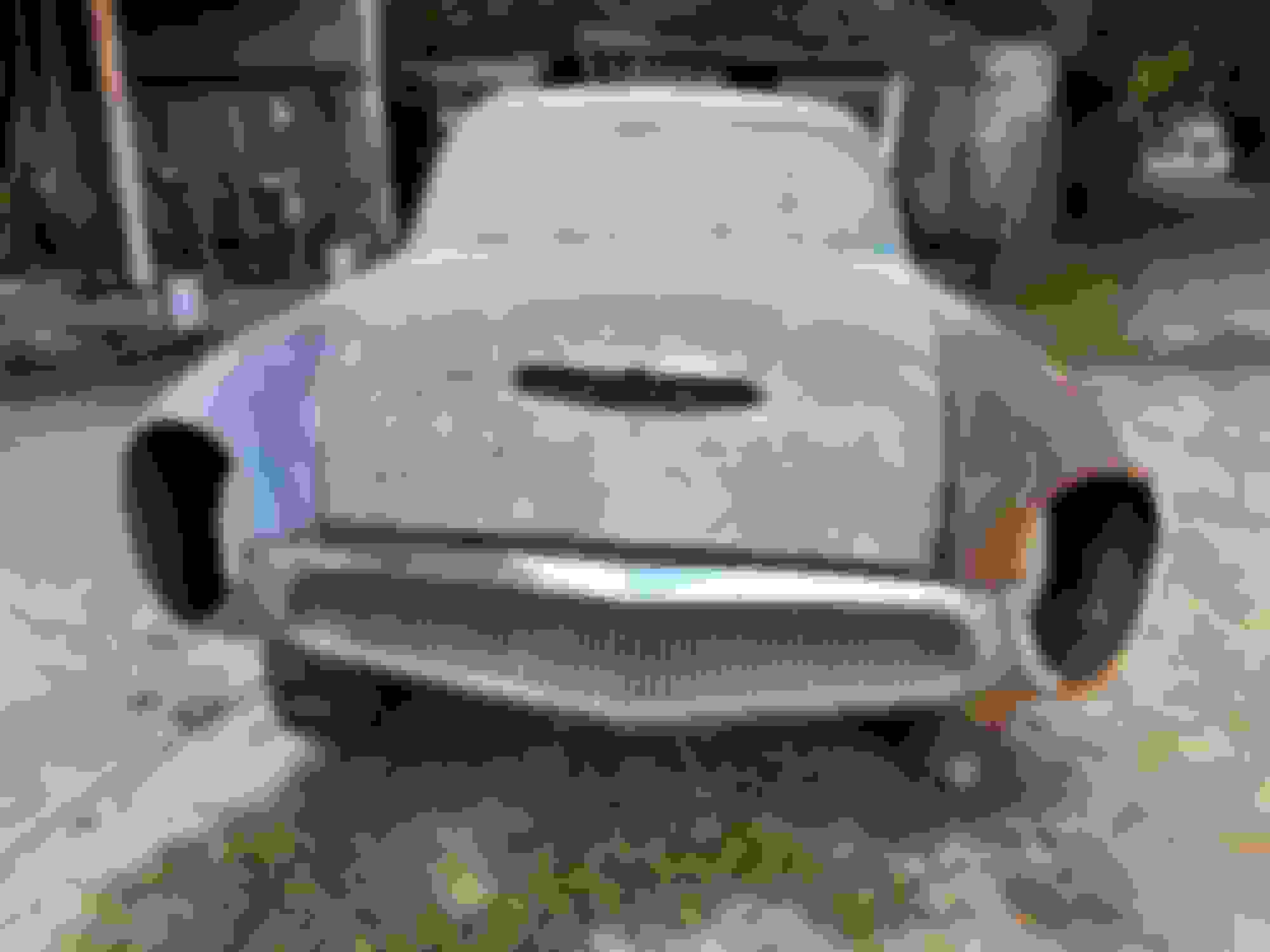
Just before the body was welded to the frame
Much progress since that first picture.
Additional info that needs your input:
The switch has separate wires for the front parking lights and rear parking lights labeled 1 and 2 so I figured that I just hook the parking lamp wire to one of those or can run a wire from each terminal connected together into one wire that would go to the lite blue wire with the white stripe. The courtesy lamps I figured on possibly wiring separately and running a wire to the terminal on the switch unless you think there is a need to use the courtesy lights associated with the Trailblazer. I am also thinking the instrument lights maybe should just be hooked up separately to the switch since there's not many lights to hook up and it's pretty straightforward. Three lights to the instrument panel and two lights to the clock in the glove box door.
Most of this depends on the total current involved vs the specs on the new switch. You might have to measure the current draw in each circuit leg and make sure the switch can handle it. The other issue is if you can now live with a more simple on off scheme for these lights vs the original functions where say interior lights came on with the door handles or the timer function after activation. Removing the BCM from the equation would make this a simple on off affair now.
I greatly appreciate your help and thank you again,
Oh and be careful to differentiate between switch terminal and actual vehicle wire color. Now that I see that color decode on the switch package we may have mixed some of this up.
What a project. When you said Kaiser, I envisioned a Kaiser *****'s jeep style, not a four door sedan. I think Mr. Kaiser would be happy and proud to see his namesake carried on. Keep us posted on your progress. Good luck , Jim
Thanks for asking. The Kaiser company was the first new American Car Company after WWII that wasn't associated with the big three. Cars also went under the name Frazier and Henry J and of course Willis. Got the idea from a guy who had a 51 Studebaker on a 98 S10 4 wheel drive frame but it still needed more work and he wanted too much for it. Found a guy who would put a Studebaker on an Escalade frame but didn't have a title for it. Looking around on Facebook market and this guy had a 55 for sale, mentioned he had a 54 for less both same body style. I went and saw it, the interior looks like it's been reupholstered but it's actually the original interior and I think he was tearing it down to get it repainted. The paint job is green and beige with the green roof being original paint job and intact but the beige needing to come off and be repainted. The guy who did the Studebaker Escalade job said he would be interested in doing this project and he's not outrageously expensive like a lot of your regular body shops are. So I got the 54 Kaiser Manhattan for 3,000 and bought the 2001 4-door Trailblazer for 1200. I wanted to have it as a regular driver and something to tow my Subarus around with. I have some late 70s early 80s Subaru brats in a few cars from the first generation that I am restoring. And by the way I'm not rich just very frugal and ended up with the number of Subarus over a number years. The car in the picture needs a bath and the one you saw before was as after it got rinsed. You can see the 55 partly in the background of two of the pictures. Hope I didn't Ramble On too much:-)