
what have you gotten done on your blazer today?
#7461
 01-18-2013, 11:29 AM


Seriously dude I love to joke around and I have the dirtiest mind of anyone I know but thats not what this forum is about!!


#7463
01-18-2013, 02:15 PM
Thats all fine and dandy but look around the forum and you will see that no one else is like that at all!!
As for what I did today I order some rocker switches they should be here early next week. I didn't work on the panel at all cause I was lazy and I forgot to grab my metal shears from home to use to cut a nice corner on it. I'll work on it on monday.
The other thing I didn't do was this!!
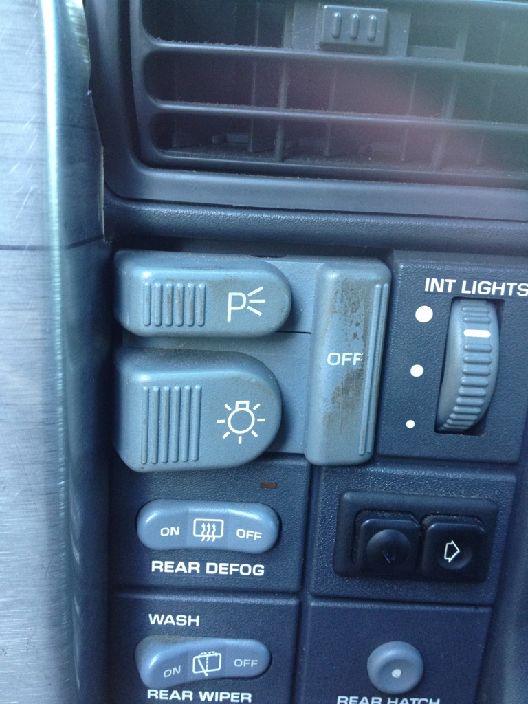
Yup thats right the switch is still dirty lol!!
As for what I did today I order some rocker switches they should be here early next week. I didn't work on the panel at all cause I was lazy and I forgot to grab my metal shears from home to use to cut a nice corner on it. I'll work on it on monday.
The other thing I didn't do was this!!
Yup thats right the switch is still dirty lol!!
#7468
01-18-2013, 03:50 PM
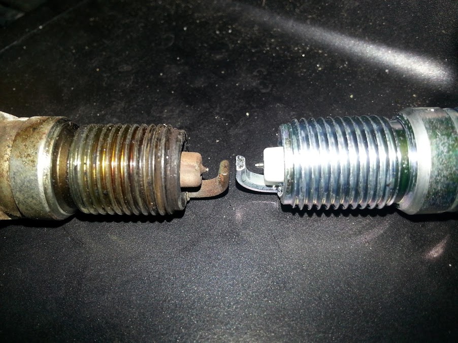
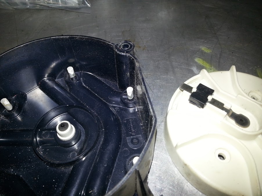
changed the plugs, cap and rotor. runs no different, mind you it ran fine before. I figured 125k kms(78k miles) and 9 years was long enough for those parts. the old cap and rotor were cheap ones, plugs were cheapest ones they had. put new cheap parts in.
the worst plug:
cap and rotor:
the worst plug:
cap and rotor:
#7469
01-18-2013, 03:54 PM

They are horrible things off-road, far more streetable than a locker though
Last edited by Diaita; 01-18-2013 at 03:56 PM.
#7470
01-18-2013, 03:56 PM
Am I reading this correctly that a g80 has charateristics of a limited slip but its actually a locking differential?
Locking Differential Description and Operation
The locking differential consists of the following components:
The optional locking differential (RPO G80) enhances the traction capability of the rear axle by combining the characteristics of a limited-slip differential and the ability of the axle shafts to “lock” together when uneven traction surfaces exist. The differential accomplishes this in 2 ways. First by having a series of clutch plates at each side of the differential case to limit the amount of slippage between each wheel. Second, by using a mechanical locking mechanism to stop the rotation of the right differential side gear, or the left differential side gear on the 10.5 inch axle, in order to transfer the rotating torque of the wheel without traction to the wheel with traction. Each of these functions occur under different conditions.
Limited-Slip Function
Under normal conditions, when the differential is not locked, a small amount of limited-slip action occurs. The gear separating force developed in the right-hand (left-hand side on 10.5 inch axle) clutch pack is primarily responsible for this.
The operation of how the limited-slip function of the unit works can be explained when the vehicle makes a right-hand turn. Since the left wheel travels farther than the right wheel, it must rotate faster than the ring gear and differential case assembly. This results in the left axle and left side gear rotating faster than the differential case. The faster rotation of the left-side gear causes the pinion gears to rotate on the pinion shaft. This causes the right-side gear to rotate slower than the differential case.
Although the side gear spreading force produced by the pinion gears compresses the clutch packs, primarily the right side, the friction between the tires and the road surface is sufficient to overcome the friction of the clutch packs. This prevents the side gears from being held to the differential case.
Locking Function
Locking action occurs through the use of some special parts:
When the wheel-to-wheel speed difference is 100 RPM or more, the flyweights of the governor will fling out and one of them will contact an edge of the latching bracket. This happens because the left cam side gear and cam plate are rotating at a speed different, either slower or faster, than that of the ring gear and differential case assembly. The cam plate has teeth on its outer diameter surface in mesh with teeth on the shaft of the governor.
As the side gear rotates at a speed different than that of the differential case, the shaft of the governor rotates with enough speed to force the flyweights outward against spring tension. One of the flyweights catches its edge on the closest edge of the latching bracket, which is stationary in the differential case. This latching process triggers a chain of events.
When the governor latches, it stops rotating. A small friction clutch inside the governor allows rotation, with resistance, of the governor shaft while one flyweight is held to the differential case through the latching bracket. The purpose of the governor's latching action is to slow the rotation of the cam plate as compared to the cam side gear. This will cause the cam plate to move out of its detent position.
The cam plate normally is held in its detent position by a small wave spring and detent humps resting in matching notches of the cam side gear. At this point, the ramps of the cam plate ride up on the ramps of the cam side gear, and the cam plate compresses the left clutch pack with a self-energizing action.
As the left clutch pack is compressed, it pushes the cam plate and cam side gear slightly toward the right side of the differential case. This movement of the cam side gear pushes the thrust block which compresses the right-hand side gear clutch pack.
At this point, the force of the self-energizing clutches and the side gear separating force combine to hold the side gears to the differential case in the locking stage.
The entire locking process occurs in less than 1 second. The process works with either the left or right wheel spinning, due to the design of the governor and cam mechanism. A torque reversal of any kind will unlatch the governor, causing the cam plate to ride back down to its detent position. Cornering or deceleration during a transmission shift will cause a torque reversal of this type. The differential unit returns to its limited-slip function.
The self-energizing process would not occur if it were not for the action of one of the left clutch discs. This energizing disc provides the holding force of the ramping action to occur. It is the only disc which is splined to the cam plate itself. The other splined discs fit on the cam side gear.
If the rotating speed of the ring gear and differential case assembly is high enough, the latching bracket will pivot due to centrifugal force. This will move the flyweights so that no locking is permitted. During vehicle driving, this happens at approximately 32 km/h (20 mph) and continues at faster speeds.
When comparing the effectiveness of the locking differential, in terms of percent-of-grade capability to open and limited-slip units, the locking differential has nearly 3 times the potential of the limited-slip unit under the same conditions.
Locking Differential Torque-Limiting Disc
The locking differential design was modified in mid-1986 to include a load-limiting feature to reduce the chance of breaking an axle shaft under abusive driving conditions. The number of tangs on the energizing disc in the left-hand clutch pack was reduced allowing these tangs to shear in the event of a high-torque engagement of the differential locking mechanism.
At the time of failure of the load-limiting disc, there will be a loud bang in the rear axle and the differential will operate as a standard differential with some limited-slip action of the clutch packs at low torques.
The service procedure, when the disc tangs shear, involves replacing the left-hand clutch plates and the wave spring. It is also necessary to examine the axle shafts for twisting because at high torques it is possible to not only shear the load-limiting disc, but to also twist the axle shafts.
Locking Differential Description and Operation
The locking differential consists of the following components:
• Differential case – 1 or 2 piece
• Locking differential spider – 2 piece case only
• Pinion gear shaft – 1 piece case only
• Differential pinion gear shaft lock bolt – 1 piece case only
• 2 clutch discs sets
• Locking differential side gear
• Thrust block
• Locking differential clutch disc guides
• Differential side gear shim
• Locking differential clutch disc thrust washer
• Locking differential governor
• Latching bracket
• Cam plate assembly
• Differential pinion gears
• Differential pinion gear thrust washers
The optional locking differential (RPO G80) enhances the traction capability of the rear axle by combining the characteristics of a limited-slip differential and the ability of the axle shafts to “lock” together when uneven traction surfaces exist. The differential accomplishes this in 2 ways. First by having a series of clutch plates at each side of the differential case to limit the amount of slippage between each wheel. Second, by using a mechanical locking mechanism to stop the rotation of the right differential side gear, or the left differential side gear on the 10.5 inch axle, in order to transfer the rotating torque of the wheel without traction to the wheel with traction. Each of these functions occur under different conditions.
Limited-Slip Function
Under normal conditions, when the differential is not locked, a small amount of limited-slip action occurs. The gear separating force developed in the right-hand (left-hand side on 10.5 inch axle) clutch pack is primarily responsible for this.
The operation of how the limited-slip function of the unit works can be explained when the vehicle makes a right-hand turn. Since the left wheel travels farther than the right wheel, it must rotate faster than the ring gear and differential case assembly. This results in the left axle and left side gear rotating faster than the differential case. The faster rotation of the left-side gear causes the pinion gears to rotate on the pinion shaft. This causes the right-side gear to rotate slower than the differential case.
Although the side gear spreading force produced by the pinion gears compresses the clutch packs, primarily the right side, the friction between the tires and the road surface is sufficient to overcome the friction of the clutch packs. This prevents the side gears from being held to the differential case.
Locking Function
Locking action occurs through the use of some special parts:
• A governor mechanism with 2 flyweights
• A latching bracket
• The left side cam plate and cam side gear
When the wheel-to-wheel speed difference is 100 RPM or more, the flyweights of the governor will fling out and one of them will contact an edge of the latching bracket. This happens because the left cam side gear and cam plate are rotating at a speed different, either slower or faster, than that of the ring gear and differential case assembly. The cam plate has teeth on its outer diameter surface in mesh with teeth on the shaft of the governor.
As the side gear rotates at a speed different than that of the differential case, the shaft of the governor rotates with enough speed to force the flyweights outward against spring tension. One of the flyweights catches its edge on the closest edge of the latching bracket, which is stationary in the differential case. This latching process triggers a chain of events.
When the governor latches, it stops rotating. A small friction clutch inside the governor allows rotation, with resistance, of the governor shaft while one flyweight is held to the differential case through the latching bracket. The purpose of the governor's latching action is to slow the rotation of the cam plate as compared to the cam side gear. This will cause the cam plate to move out of its detent position.
The cam plate normally is held in its detent position by a small wave spring and detent humps resting in matching notches of the cam side gear. At this point, the ramps of the cam plate ride up on the ramps of the cam side gear, and the cam plate compresses the left clutch pack with a self-energizing action.
As the left clutch pack is compressed, it pushes the cam plate and cam side gear slightly toward the right side of the differential case. This movement of the cam side gear pushes the thrust block which compresses the right-hand side gear clutch pack.
At this point, the force of the self-energizing clutches and the side gear separating force combine to hold the side gears to the differential case in the locking stage.
The entire locking process occurs in less than 1 second. The process works with either the left or right wheel spinning, due to the design of the governor and cam mechanism. A torque reversal of any kind will unlatch the governor, causing the cam plate to ride back down to its detent position. Cornering or deceleration during a transmission shift will cause a torque reversal of this type. The differential unit returns to its limited-slip function.
The self-energizing process would not occur if it were not for the action of one of the left clutch discs. This energizing disc provides the holding force of the ramping action to occur. It is the only disc which is splined to the cam plate itself. The other splined discs fit on the cam side gear.
If the rotating speed of the ring gear and differential case assembly is high enough, the latching bracket will pivot due to centrifugal force. This will move the flyweights so that no locking is permitted. During vehicle driving, this happens at approximately 32 km/h (20 mph) and continues at faster speeds.
When comparing the effectiveness of the locking differential, in terms of percent-of-grade capability to open and limited-slip units, the locking differential has nearly 3 times the potential of the limited-slip unit under the same conditions.
Locking Differential Torque-Limiting Disc
The locking differential design was modified in mid-1986 to include a load-limiting feature to reduce the chance of breaking an axle shaft under abusive driving conditions. The number of tangs on the energizing disc in the left-hand clutch pack was reduced allowing these tangs to shear in the event of a high-torque engagement of the differential locking mechanism.
At the time of failure of the load-limiting disc, there will be a loud bang in the rear axle and the differential will operate as a standard differential with some limited-slip action of the clutch packs at low torques.
The service procedure, when the disc tangs shear, involves replacing the left-hand clutch plates and the wave spring. It is also necessary to examine the axle shafts for twisting because at high torques it is possible to not only shear the load-limiting disc, but to also twist the axle shafts.